AIR CONDITIONING SYSTEM(for Manual Air Conditioning System) SYSTEM DESCRIPTION
-
GENERAL (w/ Cooler)
The air conditioning system has the following controls:
Control Outline Variable Capacity Compressor Control Controls the compressor to turn ON or OFF and the discharge capacity based on the signals from various sensors. -
MODE POSITION AND DAMPER OPERATION (w/ Cooler)
-
Mode position and damper operation
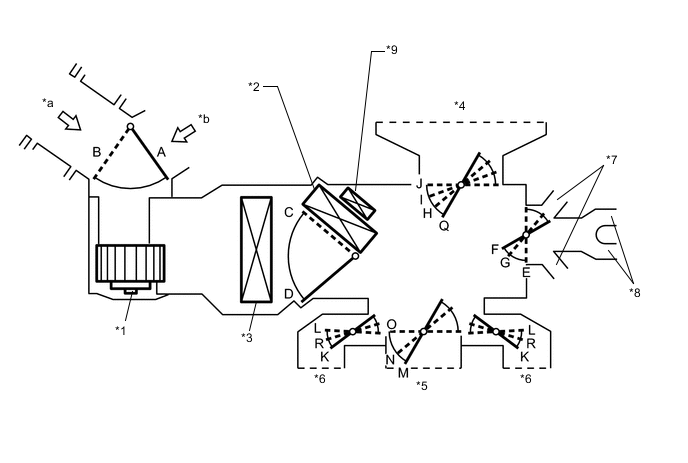
Text in Illustration *1 Blower Motor with Fan Sub-Assembly *2 Heater Radiator Unit Sub-Assembly *3 No. 1 Cooler Evaporator Sub-Assembly *4 Front Defroster *5 Center Register *6 Side Register *7 Front Footwell Register Duct *8 Rear Footwell Register Duct *9 Quick Heater Assembly - - *a Fresh Air *b Recirculated Air Tech Tips
This Illustration is damper operation image. The number and location of the dampers is different to the actual unit.
Functions of Main Dampers Control Damper Operation Position Damper Position Operation Air Inlet Control Damper FRESH A Allows outside air to enter. RECIRC B Recirculates internal air. Air Mix Control Damper MAX COLD to MAX HOT Temperature Setting C, D Continuously changes mix ratio of warm and cool air between COOL and HOT. Mode Control Damper DEF

O, R, E, Q Blows air from front defroster and side registers. FOOT / DEF

O, K, G, H Blows air from front defroster, side registers, front footwell register and rear footwell register. FOOT

O, K, F, I Blows air from side registers, front footwell register and rear footwell register. Also, blows some air from front defroster. BI-LEVEL

N, R, F, J Blows air from center register, side registers, front footwell register and rear footwell register. FACE

M, L, E, J Blows air from center register and side registers.
-
-
MODE POSITION AND DAMPER OPERATION (w/o Cooler)
-
Mode position and damper operation
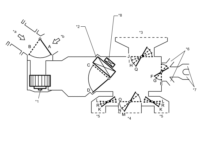
Text in Illustration *1 Blower Motor with Fan Sub-Assembly *2 Heater Radiator Unit Sub-Assembly *3 Front Defroster *4 Center Register *5 Side Register *6 Front Footwell Register Duct *7 Rear Footwell Register Duct *8 Quick Heater Assembly *a Fresh Air *b Recirculated Air Tech Tips
This Illustration is damper operation image. The number and location of the dampers is different to the actual unit.
Functions of Main Dampers Control Damper Operation Position Damper Position Operation Air Inlet Control Damper FRESH A Allows outside air to enter. RECIRC B Recirculates internal air. Air Mix Control Damper MIN HOT to MAX HOT Temperature Setting C, D Continuously changes ratio of warm air. Mode Control Damper DEF
O, R, E, Q Blows air from front defroster and side registers. FOOT / DEF
O, K, G, H Blows air from front defroster, side registers, front footwell register and rear footwell register. FOOT
O, K, F, I Blows air from side registers, front footwell register and rear footwell register. Also, blows some air from front defroster. BI-LEVEL
N, R, F, J Blows air from center register, side registers, front footwell register and rear footwell register. FACE
M, L, E, J Blows air from center register and side registers.
-
-
AIR OUTLET AND AIRFLOW VOLUME
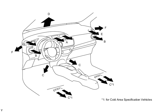
Air Outlet Mode Air Outlet Position Symbol A B C D E F Center Face Side Face Foot Defroster Side Defroster Side Defroster FACE 
- - - - BI - LEVEL 
- - - FOOT - 
FOOT/DEF - DEF - - The size of the circle ○ indicates the proportion of airflow volume.