AIR CONDITIONING SYSTEM(for Automatic Air Conditioning System) PTC Heater Circuit
DESCRIPTION
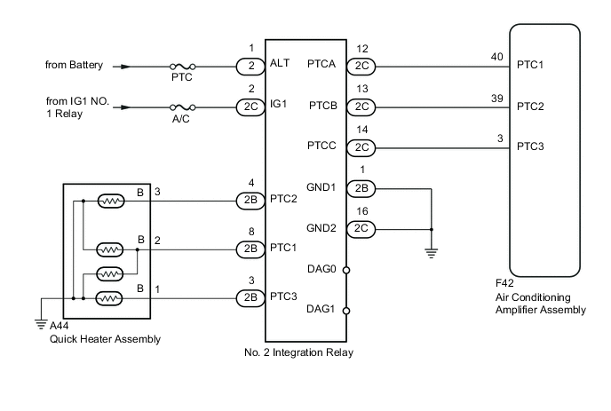
The No. 2 integration relay is controlled in accordance with signals from the air conditioning amplifier assembly and power is supplied to the quick heater assembly installed on the radiator heater unit.
WIRING DIAGRAM
CAUTION / NOTICE / HINT
Note
Inspect the fuses for circuits related to this system before performing the following inspection procedures.
PROCEDURE
-
PERFORM ACTIVE TEST USING INTELLIGENT TESTER
-
Connect the intelligent tester to the DLC3.
-
Turn the ignition switch to ON.
-
Turn the intelligent tester on.
-
Enter the following menus: Body / Air Conditioner / Active Test.
-
According to the display on the intelligent tester, perform the Active Test.
Air Conditioner Tester Display Test Part Control Range Diagnostic Note Heater Active Level Heater level Min.: 0, Max.: 3 - -
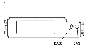
Text in Illustration *a Upper View of No. 2 Integration Relay Measure the voltage according to the value(s) in the table below while performing the Active Test.
Standard Voltage Tester Connection Condition Specified Condition 0 (DAG0) - Body ground Heater Active Level 1 to 3 3.5 to 5 V 1 (DAG1) - Body ground Heater Active Level 1 to 3 3.5 to 5 V
NG 
CHECK HARNESS AND CONNECTOR (NO. 2 INTEGRATION RELAY - BATTERY AND IG1 NO. 1 RELAY) Click here
OK 
-
-
INSPECT QUICK HEATER ASSEMBLY
-
Inspect the quick heater assembly Click here.
NG 
REPLACE QUICK HEATER ASSEMBLY Click here
OK
-
-
PERFORM ACTIVE TEST USING INTELLIGENT TESTER
-
Disconnect the A44 quick heater assembly connector.
-
Connect the intelligent tester to the DLC3.
-
Start the engine.
-
Turn the intelligent tester on.
-
Enter the following menus: Body / Air Conditioner / Active Test.
-
According to the display on the intelligent tester, perform the Active Test.
Air Conditioner Tester Display Test Part Control Range Diagnostic Note Heater Active Level Heater level Min.: 0, Max.: 3 - -
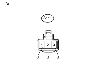
Text in Illustration *a Front view of wire harness connector
(to Quick Heater Assembly)
Measure the voltage according to the value(s) in the table below while performing the Active Test.
Standard Voltage Tester Connection Condition Specified Condition A44-1 (B) - Body ground Heater Active Level 0 Below 1 V Heater Active Level 1 Below 1 V Heater Active Level 2 Below 1 V Heater Active Level 3 11 to 14 V A44-2 (B) - Body ground Heater Active Level 0 Below 1 V Heater Active Level 1 11 to 14 V Heater Active Level 2 11 to 14 V Heater Active Level 3 11 to 14 V A44-3 (B) - Body ground Heater Active Level 0 Below 1 V Heater Active Level 1 Below 1 V Heater Active Level 2 11 to 14 V Heater Active Level 3 11 to 14 V
OK
PROCEED TO NEXT SUSPECTED AREA SHOWN IN PROBLEM SYMPTOMS TABLE Click here
NG
REPAIR OR REPLACE HARNESS OR CONNECTOR (QUICK HEATER ASSEMBLY - NO. 2 INTEGRATION RELAY)
-
-
CHECK HARNESS AND CONNECTOR (NO. 2 INTEGRATION RELAY - BATTERY AND IG1 NO. 1 RELAY)
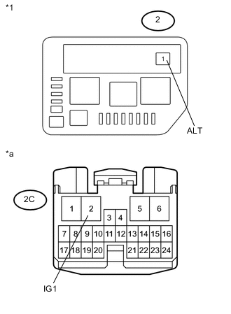
Text in Illustration *1 No. 2 Engine Room Relay Block *a Front view of wire harness connector
(to No. 2 Integration Relay)
-
Remove the No. 2 integration relay from the No. 2 engine room relay block.
-
Measure the voltage according to the value(s) in the table below.
Standard Voltage Tester Connection Switch Condition Specified Condition 2-1 (ALT) - Body ground Always 11 to 14 V 2C-2 (IG1) - Body ground Ignition switch ON 11 to 14 V
NG
REPAIR OR REPLACE HARNESS OR CONNECTOR
OK
-
-
CHECK HARNESS AND CONNECTOR (NO. 2 INTEGRATION RELAY - BODY GROUND)
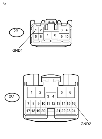
Text in Illustration *a Front view of wire harness connector
(to No. 2 Integration Relay)
-
Remove the No. 2 integration relay from the No. 2 engine room relay block.
-
Measure the resistance according to the value(s) in the table below.
Standard Resistance Tester Connection Condition Specified Condition 2B-1 (GND1) - Body ground Always Below 1 Ω 2C-16 (GND2) - Body ground Always Below 1 Ω
NG
REPAIR OR REPLACE HARNESS OR CONNECTOR
OK
-
-
PERFORM ACTIVE TEST USING INTELLIGENT TESTER
-
Remove the No. 2 integration relay from the No. 2 engine room relay block.
-
Connect the intelligent tester to the DLC3.
-
Start the engine.
-
Turn the intelligent tester on.
-
Enter the following menus: Body / Air Conditioner / Active Test.
-
According to the display on the intelligent tester, perform the Active Test.
Air Conditioner Tester Display Test Part Control Range Diagnostic Note Heater Active Level Heater level Min.: 0, Max.: 3 - -
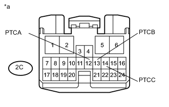
Text in Illustration *a Front view of wire harness connector
(to No. 2 Integration Relay)
Measure the voltage according to the value(s) in the table below while performing the Active Test.
Standard Voltage Tester Connection Condition Specified Condition 2C-12 (PTCA) - Body ground Heater Active Level 0 Below 1 V Heater Active Level 1 11 to 14 V Heater Active Level 2 11 to 14 V Heater Active Level 3 11 to 14 V 2C-13 (PTCB) - Body ground Heater Active Level 0 Below 1 V Heater Active Level 1 Below 1 V Heater Active Level 2 11 to 14 V Heater Active Level 3 11 to 14 V 2C-14 (PTCC) - Body ground Heater Active Level 0 Below 1 V Heater Active Level 1 Below 1 V Heater Active Level 2 Below 1 V Heater Active Level 3 11 to 14 V
OK
REPLACE NO. 2 INTEGRATION RELAY
NG
-
-
CHECK HARNESS AND CONNECTOR (NO. 2 INTEGRATION RELAY - AIR CONDITIONING AMPLIFIER ASSEMBLY)
-
Remove the No. 2 integration relay from the No. 2 engine room relay block.
-
Disconnect the F42 air conditioning amplifier assembly connector.
-
Measure the resistance according to the value(s) in the table below.
Standard Resistance Tester Connection Condition Specified Condition 2C-12 (PTCA) - F42-40 (PTC1) Always Below 1 Ω 2C-13 (PTCB) - F42-39 (PTC2) Always Below 1 Ω 2C-14 (PTCC) - F42-3 (PTC3) Always Below 1 Ω 2C-12 (PTCA) - Body ground Always 10 kΩ or higher 2C-13 (PTCB) - Body ground Always 10 kΩ or higher 2C-14 (PTCC) - Body ground Always 10 kΩ or higher
OK
REPLACE AIR CONDITIONING AMPLIFIER ASSEMBLY Click here
NG
REPAIR OR REPLACE HARNESS OR CONNECTOR
-