| DTC Code | DTC Name |
|---|---|
| B1497/97 | BUS IC Communication Malfunction |
DESCRIPTION
The air conditioning harness assembly connects the air conditioning amplifier assembly and each servo motor. The air conditioning amplifier assembly supplies power and sends operation instructions to each servo motor through the air conditioning harness assembly. Each servo motor sends the damper position information to the air conditioning amplifier assembly.
| DTC No. | DTC Detection Condition | Trouble Area |
|---|---|---|
| B1497/97 | An open circuit or malfunction in the communication line. |
|
CAUTION / NOTICE / HINT
Inspect the fuses for circuits related to this system before performing the following inspection procedure.
PROCEDURE
- Click here
CHECK HARNESS AND CONNECTOR (AIR CONDITIONING AMPLIFIER ASSEMBLY - BATTERY AND BODY GROUND)
-
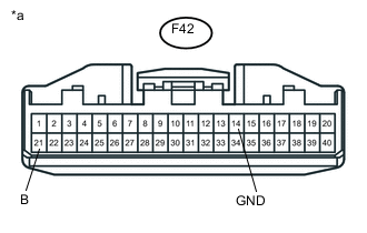
Disconnect the F42 air conditioning amplifier assembly connector.
-
Measure the voltage according to the value(s) in the table below.
Standard Voltage Tester Condition Condition Specified Condition F42-21 (B) - Body ground Always 11 to 14 V -
Measure the resistance according to the value(s) in the table below.
Standard Resistance Tester Condition Condition Specified Condition F42-14 (GND) - Body ground Always Below 1 Ω Table 1. Text in Illustration *a Rear view of wire harness connector
(to Air Conditioning Amplifier Assembly)
- OKClick here
- NG
REPAIR OR REPLACE HARNESS OR CONNECTOR
-
- Click here
CHECK AIR CONDITIONING AMPLIFIER ASSEMBLY
-
Reconnect the air conditioning amplifier assembly connector.
-
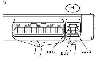
Remove the air conditioning amplifier assembly with its connectors still connected (Click here).
-
Measure the resistance according to the value(s) in the table below.
Standard Resistance Tester Connection Condition Specified Condition z4-2 (BUSG) - Body ground Always Below 1 Ω -
Measure the voltage according to the value(s) in the table below.
Standard Voltage Tester Connection Switch Condition Specified Condition z4-4 (BBUS) - z4-2 (BUSG) Ignition switch ON 11 to 14 V z4-3 (BUS) - z4-2 (BUSG) Ignition switch ON Pulse generation Table 2. Text in Illustration *a Component with harness connected
(Air Conditioning Amplifier Assembly)
Table 3. Result Result Proceed to OK (When troubleshooting according to the DTC) A OK (When troubleshooting according to Problem Symptoms Table) B NG C
- A
REPLACE AIR CONDITIONING HARNESS ASSEMBLY (Click here)
- B
PROCEED TO NEXT SUSPECTED AREA SHOWN IN PROBLEM SYMPTOMS TABLE (Click here)
- C
REPLACE AIR CONDITIONING AMPLIFIER ASSEMBLY (Click here)
-