Click here
-

CHECK AIR CONDITIONING AMPLIFIER ASSEMBLY
Tip:Check from the rear of the connector while it is connected to the air conditioning amplifier assembly.
Terminal No. (Symbol) Wiring Color Terminal Description Condition Specified Condition F42-1 (IG+) - F42-14 (GND) V - W-B Ignition power supply Ignition switch: ON 11 to 14 V F42-2 (SOL+) - F42-14 (GND) P - W-B A/C compressor operation signal Engine idling Pulse generation
(See waveform 1)
Blower switch: LO A/C switch: ON F42-9 (PRE) - F42-14 (GND) GR - W-B Air conditioning pressure sensor signal Refrigerant pressure: Normal 0.74 to 4.62 V Refrigerant pressure: Abnormal (less than 0.176 MPaG [1.8 kgf/cm2]) or more than 3.03 MPaG [31 kgf/cm2])
Below 0.74 V or 4.62 V or more F42-10 (S5-3) - F42-14 (GND) Y - W-B Power supply for pressure sensor Ignition switch: ON 4.75 to 5.25 V F42-11 (TX+) - F42-14 (GND) V - W-B CAN communication signal Ignition switch: ON Pulse generation
(See waveform 2)
F42-12 (TX-) - F42-14 (GND) W - W-B CAN communication signal Ignition switch: ON Pulse generation
(See waveform 3)
F42-13 (SG-2) - Body ground L - Body ground Ground for A/C pressure sensor Always Below 1 Ω F42-14 (GND) - Body ground W-B - Body ground Ground for main power supply Always Below 1 Ω F42-21 (B) - F42-14 (GND) BE - W-B Battery power supply Always 11 to 14 V F42-40 (PTC1) - Body ground*1 V - Body ground No. 2 integration relay operation signal Engine idling 11 to 14 V → Below 1 V Set temperature: MAX HOT Engine coolant temperature: Below 75°C (167°F) Ambient temperature: Below 10°C (50°F) Blower switch: OFF → LO Waiting time: 10 seconds F42-39 (PTC2) - Body ground*1 P - Body ground No. 2 integration relay operation signal Engine idling 11 to 14 V → Below 1 V Set temperature: MAX HOT Engine coolant temperature: Below 70°C (158°F) Ambient temperature: Below 10°C (50°F) Blower switch: OFF → LO Waiting time: 20 seconds F42-3 (PTC3) - Body ground*1 Y - Body ground No. 2 integration relay operation signal Engine idling 11 to 14 V → Below 1 V Set temperature: MAX HOT Engine coolant temperature: Below 65°C (149°F) Ambient temperature: Below 10°C (50°F) Blower switch: OFF → LO Waiting time: 30 seconds F42-22 (BLW) - F42-14 (GND) R - W-B Blower motor control signal Ignition switch: ON Pulse generation
(See waveform 4)
Blower switch: LO F42-29 (TR) - F42-34 (SG-1) P - SB Room temperature sensor signal Ignition switch: ON 1.8 to 2.2 V Vehicle interior temperature: 25°C F42-30 (S5-1) - F42-14 (GND)*2 L - W-B Solar sensor power supply Ignition switch: ON 4.5 to 5.5 V F42-33 (TSD) - F42-14 (GND) R - W-B Solar sensor signal Ignition switch: ON 0.8 to 4.3 V Solar sensor subject to electric light F42-34 (SG-1) - Body ground SB - Body ground Ground for room temperature sensor Always Below 1 Ω F42-37 (LIN1) - F42-14 (GND) LG - W-B LIN communication signal Ignition switch: ON Pulse generation z4-2 (BUSG) - Body ground - Ground for BUS IC Always Below 1 Ω z4-3 (BUS) - z4-2 (BUSG) - BUS IC control signal Ignition switch: ON Pulse generation z4-4 (BBUS) - z4-2 (BUSG) - BUS IC power supply Always 11 to 14 V z4-5 (SGA) - Body ground - Ground for evaporator temperature sensor Always Below 1 Ω z4-6 (TEA) - z4-5 (SGA) - Evaporator temperature sensor signal Ignition switch: ON 1.4 to 1.8 V Evaporator temperature: 15°C (59°F)
-
*1: w/ PTC Heater
-
*2: w/o Automatic Light Control System
-
If the result is not as specified, there may be a malfunction in the wire harness.
-
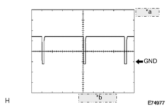
Table 1. *a 5 V/DIV. *b 500 μsec/DIV. Waveform 1: Using an oscilloscope
Table 2. Compressor and Pulley Operation Signal Terminal Name F42-2 (SOL+) - F42-14 (GND) Tester Range 5 V/DIV, 500 μs/DIV Condition Engine idling
Blower switch LO
A/C switch ON
-
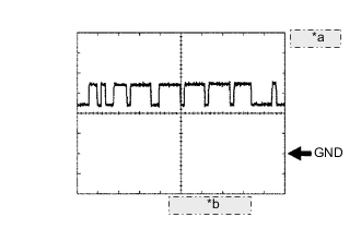
Table 3. *a 1 V/DIV. *b 10 μsec./DIV. Waveform 2 (Reference) : Using an oscilloscope
Table 4. CAN Communication Signal Terminal Name F42-11 (TX+) - F42-14 (GND) Tester Range 1 V/DIV, 10 μs/DIV Condition Ignition switch ON Tip:The waveform varies depending on the CAN communication signal.
-
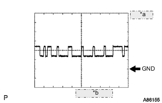
Table 5. *a 1 V/DIV. *b 10 μsec./DIV. Waveform 3 (Reference) : Using an oscilloscope
Table 6. CAN Communication Signal Terminal Name F42-12 (TX-) - F42-14 (GND) Tester Range 1 V/DIV, 10 μs/DIV Condition Ignition switch ON Tip:The waveform varies depending on the CAN communication signal.
-
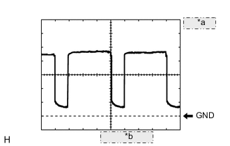
Table 7. *a 1 V/DIV. *b 500 μsec/DIV. Waveform 4: Using an oscilloscope.
Table 8. Blower Motor Control Signal Terminal Name F42-22 (BLW) - F42-14 (GND) Tester Range 1 V/DIV, 500 μs/DIV Condition Ignition switch ON
Blower switch LO
Tip:When the blower level is increased, the duty ratio changes accordingly.
-
-
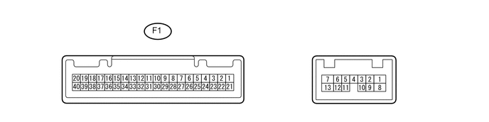
CHECK COMBINATION METER ASSEMBLY
Tip:Check from the rear of the connector while it is connected to the combination meter assembly.
Terminal No. (Symbol) Wiring Color Terminal Description Condition Specified Condition F1-34 (TX1-) - Body ground B - Body ground Ground for ambient temperature sensor Always Below 1 Ω F1-35 (TX1+) - F1-34 (TX1-) W - B Ambient temperature sensor signal Ignition switch ON at 25°C (77°F) 1.35 to 1.75 V F1-39 (IG+) - Body ground P - Body ground Ignition power supply Ignition switch ON 11 to 14 V F1-40 (B) - Body ground L - Body ground Battery power supply Always 11 to 14 V
-
If the result is not as specified, there may be a malfunction in the wire harness.
-
-

CHECK AIR CONDITIONING CONTROL ASSEMBLY
Terminal No. (Symbol) Wiring Color Terminal Description Condition Specified Condition F40-5 (IG+) - F40-8 (GND) V - BR Ignition power supply Ignition switch: ON 11 to 14 V F40-3 (LIN1) - F40-8 (GND) LG - BR LIN communication signal Ignition switch: ON Pulse generation F40-8 (GND) - Body ground BR - Body Ground Ground for air conditioning control assembly Always Below 1 Ω
-
If the result is not as specified, there may be a malfunction in the wire harness.
-