SEAT BELT WARNING SYSTEM Rear Seat Belt Warning Light Malfunction
DESCRIPTION
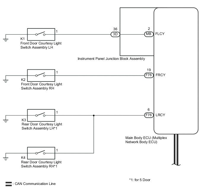
When a rear door*1 or front door*2 is opened and closed (the rear door courtesy light switch*1 or front door courtesy light switch*2 turns on and off) with the ignition switch ON, or when the ignition switch is turned from off to ON, the rear seat belt warning light in the telltale light assembly turns on to inform the driver of the rear seat belt condition. If a rear seat belt is fastened or unfastened, the warning light changes to indicate the current rear seat belt condition.
*1: for 5 Door
*2: for 3 Door
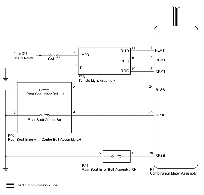
WIRING DIAGRAM
Note
Since the seat belt warning system has functions that use CAN communication, first confirm that there is no malfunction in the communication system by inspecting the CAN communication functions in accordance with How to Proceed with Troubleshooting. Then conduct the following troubleshooting procedure.
CAUTION / NOTICE / HINT
Note
Inspect the fuses for circuits related to this system before performing the following inspection procedure.
PROCEDURE
-
SYSTEM CHECK
-
Check the vehicle specifications.
Result Result Proceed to for 3 Door A for 5 Door B
B 
READ VALUE USING INTELLIGENT TESTER (REAR DOOR COURTESY LIGHT SWITCH) Click here
A 
-
-
READ VALUE USING INTELLIGENT TESTER (FRONT DOOR COURTESY LIGHT SWITCH)
-
Connect the intelligent tester to the DLC3.
-
Turn the ignition switch to ON.
-
Turn the intelligent tester on.
-
Enter the following menus: Body / Main Body / Data List.
-
According to the display on the intelligent tester, read the Data List.
Main Body Tester Display Measurement Item/Range Normal Condition Diagnostic Note FR Door Courtesy Front door courtesy light switch RH signal / ON or OFF ON: Front door RH closed
OFF: Front door RH opened
- FL Door Courtesy Front door courtesy light switch LH signal / ON or OFF ON: Front door LH closed
OFF: Front door LH opened
- OK Normal conditions listed above are displayed. Result Result Proceed to NG A OK B
A 
GO TO DOOR COURTESY SWITCH CIRCUIT Click here
B
READ VALUE USING INTELLIGENT TESTER (REAR SEAT BELT BUCKLE SWITCH) Click here
-
-
READ VALUE USING INTELLIGENT TESTER (REAR DOOR COURTESY LIGHT SWITCH)
-
Connect the intelligent tester to the DLC3.
-
Turn the ignition switch to ON.
-
Turn the intelligent tester on.
-
Enter the following menus: Body / Main Body / Data List.
-
According to the display on the intelligent tester, read the Data List.
Main Body Tester Display Measurement Item/Range Normal Condition Diagnostic Note RR Door Courtesy SW Rear door courtesy light switch LH and RH signal / ON or OFF ON: Rear door LH or RH opened
OFF: Rear door LH and RH closed
- RL Door Courtesy SW Rear door courtesy light switch LH and RH signal / ON or OFF ON: Rear door LH or RH opened
OFF: Rear door LH and RH closed
- OK Normal conditions listed above are displayed.
NG
GO TO DOOR COURTESY SWITCH CIRCUIT Click here
OK
-
-
READ VALUE USING INTELLIGENT TESTER (REAR SEAT BELT BUCKLE SWITCH)
-
Connect the intelligent tester to the DLC3.
-
Turn the ignition switch to ON.
-
Turn the intelligent tester on.
-
Enter the following menus: Body / Combination Meter / Data List.
-
According to the display on the intelligent tester, read the Data List.
Combination Meter Tester Display Measurement Item/Range Normal Condition Diagnostic Note 2nd-Row Seatbelt Buckle (R) Rear seat belt buckle RH signal / ON or OFF ON: Rear seat belt RH fastened
OFF: Rear seat belt RH unfastened
- 2nd-Row Seatbelt Buckle (L) Rear seat belt buckle LH signal / ON or OFF ON: Rear seat belt LH fastened
OFF: Rear seat belt LH unfastened
- 2nd-Row Seatbelt Buckle (C) Rear seat center belt buckle signal / ON or OFF ON: Rear seat center belt fastened
OFF: Rear seat center belt unfastened
- OK Normal conditions listed above are displayed.
NG
INSPECT REAR SEAT INNER WITH CENTER BELT ASSEMBLY LH Click here
OK
-
-
INSPECT TELLTALE LIGHT ASSEMBLY
-
Remove the telltale light assembly Click here.
-
Inspect the telltale light assembly Click here.
NG
REPLACE TELLTALE LIGHT ASSEMBLY Click here
OK
-
-
CHECK HARNESS AND CONNECTOR (TELLTALE LIGHT ASSEMBLY - COMBINATION METER ASSEMBLY)
-
Disconnect the combination meter assembly connector.
-
Measure the resistance according to the value(s) in the table below.
Standard Resistance Tester Connection Condition Specified Condition F1-1 (RLMT) - F93-11 (RLID) Always Below 1 Ω F1-2 (RCMT) - F93-9 (RCID) Always Below 1 Ω F1-3 (RRMT) - F93-10 (RRID) Always Below 1 Ω F93-5 (E) - Body ground Always Below 1 Ω F93-11 (RLID) - Body ground Always 10 kΩ or higher F93-9 (RCID) - Body ground Always 10 kΩ or higher F93-10 (RRID) - Body ground Always 10 kΩ or higher
NG
REPAIR OR REPLACE HARNESS OR CONNECTOR
OK
-
-
CHECK TELLTALE LIGHT ASSEMBLY (REAR SEAT BELT WARNING LIGHT SOURCE VOLTAGE)
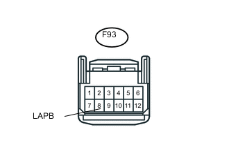
Text in Illustration *1 Front view of wire harness connector
(to Telltale Light Assembly)
-
Connect the combination meter assembly connector to the combination meter assembly.
-
Connect the negative (-) terminal cable to the battery, and wait for at least 2 seconds.
-
Turn the ignition switch to ON.
-
Measure the voltage according to the value(s) in the table below.
Standard Voltage Tester Connection Switch Condition Specified Condition F93-8 (LAPB) - Body ground Ignition switch ON 11 to 14 V
OK
REPLACE COMBINATION METER ASSEMBLY Click here
NG
REPAIR OR REPLACE HARNESS OR CONNECTOR
-
-
INSPECT REAR SEAT INNER WITH CENTER BELT ASSEMBLY LH
-
Remove the rear seat inner with center belt assembly LH Click here.
-
Inspect the rear seat inner with center belt assembly LH Click here.
NG
REPLACE REAR SEAT INNER WITH CENTER BELT ASSEMBLY LH Click here
OK
-
-
INSPECT REAR SEAT INNER BELT ASSEMBLY RH
-
Remove the rear seat inner belt assembly RH Click here.
-
Inspect the rear seat inner belt assembly RH Click here.
NG
REPLACE REAR SEAT INNER BELT ASSEMBLY RH Click here
OK
-
-
CHECK HARNESS AND CONNECTOR (REAR SEAT INNER BELT LH - COMBINATION METER AND BODY GROUND)
-
Disconnect the rear seat inner with center belt assembly LH connector.
-
Disconnect the combination meter assembly connector.
-
Measure the resistance according to the value(s) in the table below.
Standard Resistance Tester Connection Condition Specified Condition K40-2 - F1-24 (RLSB) Always Below 1 Ω K40-3 - Body ground Always Below 1 Ω K40-2 - Body ground Always 10 kΩ or higher
NG
REPAIR OR REPLACE HARNESS OR CONNECTOR
OK
-
-
CHECK HARNESS AND CONNECTOR (REAR SEAT CENTER BELT - COMBINATION METER AND BODY GROUND)
-
Disconnect the rear seat inner with center belt assembly LH connector.
-
Measure the resistance according to the value(s) in the table below.
Standard Resistance Tester Connection Condition Specified Condition K40-4 - F1-25 (RCSB) Always Below 1 Ω K40-5 - Body ground Always Below 1 Ω K40-4 - Body ground Always 10 kΩ or higher
NG
REPAIR OR REPLACE HARNESS OR CONNECTOR
OK
-
-
CHECK HARNESS AND CONNECTOR (REAR SEAT INNER BELT ASSEMBLY RH - COMBINATION METER AND BODY GROUND)
-
Disconnect the rear seat inner belt assembly RH connector.
-
Measure the resistance according to the value(s) in the table below.
Standard Resistance Tester Connection Condition Specified Condition K41-1 - F1-26 (RRSB) Always Below 1 Ω K41-2 - Body ground Always Below 1 Ω K41-1 - Body ground Always 10 kΩ or higher
OK
REPLACE COMBINATION METER ASSEMBLY Click here
NG
REPAIR OR REPLACE HARNESS OR CONNECTOR
-