STEERING PAD(for TMMF Made) REMOVAL

CAUTION / NOTICE / HINT
CAUTION:
Some of these service operations affect the SRS airbag system. Read the precautionary notices concerning the SRS airbag system before servicing.
PROCEDURE
-
PRECAUTION
Note
After turning the ignition switch off, waiting time may be required before disconnecting the cable from battery terminal. Therefore, make sure to read the disconnecting the cable from the battery terminal notice before proceeding with work Click here.
-
DISCONNECT CABLE FROM NEGATIVE BATTERY TERMINAL
CAUTION:
Wait at least 90 seconds after disconnecting the cable from the negative (-) battery terminal to disable the SRS system.
Note
When disconnecting the cable, some systems need to be initialized after the cable is reconnected.
-
REMOVE LOWER NO. 2 STEERING WHEEL COVER (for GRMN)
-
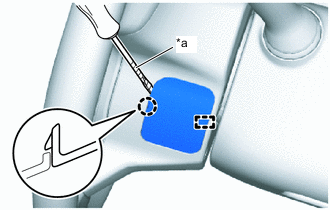
*a Protective Tape Using a screwdriver with its tip wrapped with protective tape, disengage the claw and guide to remove the lower No. 2 steering wheel cover.
-
-
REMOVE LOWER NO. 3 STEERING WHEEL COVER (for GRMN)
-
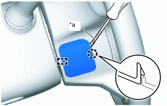
*a Protective Tape Using a screwdriver with its tip wrapped with protective tape, disengage the claw and guide to remove the lower No. 3 steering wheel cover.
-
-
REMOVE STEERING PAD (except GRMN)
-
Check that the ignition switch is off.
-
Check that the cable is disconnected from the negative (-) battery terminal.
CAUTION:
Wait at least 90 seconds after disconnecting the cable from the negative (-) battery terminal todisable the SRS system.
-
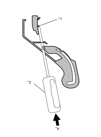
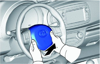
Text in Illustration *1 Retaining Clip *2 "TORX" driver *a Push Insert a flat "TORX" driver into the service hole on the lower part the steering wheel assembly as shown in the illustration.
-
Push in the retaining clip with the flat position of the "TORX" driver head and disengage the retaining hook from the retaining clip at the lower part of the steering pad.
Note
Do not push too hard, otherwise you might damage the retaining clip.
Tech Tips
The steering pad is fixed to the steering wheel by using 3 retaining clips as shown in the illustration.
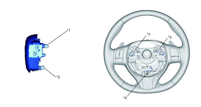
Text in Illustration *1 Retaining hooks 2 at the upper side *2 Retaining hooks 1 at the lower side *3 Upper side 2 retainer holes w/ retaining clips *4 Lower side 1 retainer hole w/ retaining clip -
After making sure the retaining clip has disengaged from the retaining hook at the lower part of the steering pad, lift up the lower part of the steering pad.
-
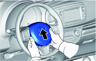
Slightly push the steering pad into the direction of the upper part of the steering wheel.
-
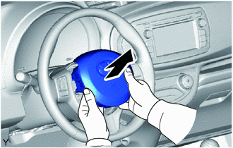
Remove the steering pad from the steering wheel hub portion.
-
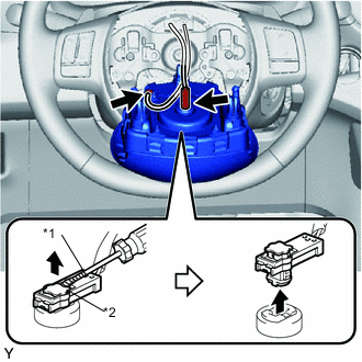
Text in Illustration *1 Protective Tape *2 Locking Button Using a screwdriver with its tip wrapped in protective tape, release the locking button.
-
Using a screwdriver with its tip wrapped in protective tape, disconnect the connector.
-
Disconnect the horn terminal.
-
-
REMOVE STEERING PAD (for GRMN)
-
Check that the ignition switch is off.
-
Check that the cable is disconnected from the negative (-) battery terminal.
CAUTION:
Wait at least 90 seconds after disconnecting the cable from the negative (-) battery terminal to disable the SRS system.
-
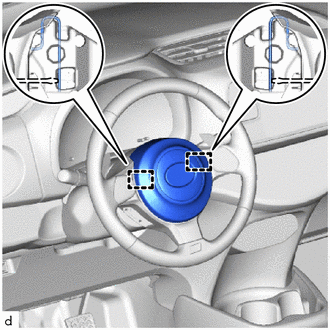
Using a screwdriver, push in the 2 snap rings to disengage it from the 2 pins.
-
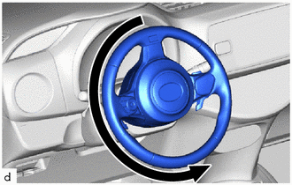
Turn the steering wheel assembly 180° to the left.
-
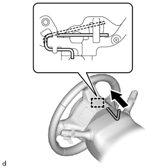
Using the 3 mm hexagon wrench, push in the snap rings to disengage it from the pin as shown in the illustration.
Note
Lightly hold the steering pad to prevent it from falling.
Tech Tips
Make sure to insert the 3 mm hexagon wrench into the service hole on the backside of the steering wheel assembly.
-
Turn the steering wheel assembly 180° to the right to align the front wheels facing straight ahead.
Note
Do not drop the horn button assembly.
-
Pull out the horn button assembly from the steering wheel assembly and hold the horn button assembly with one hand.
Note
When separating the horn button assembly, do not pull the airbag wire harness.
-
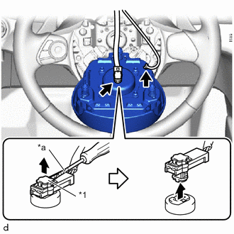
*1 Locking Button *a Protective Tape Using a screwdriver with its tip wrapped with protective tape, release the locking button.
-
Disconnect the airbag connector.
Note
When disconnecting the airbag connector, take care not to damage the airbag wire harness.
-
Disconnect the horn terminal.
-