CAUTION / NOTICE / HINT
Inspect the fuses for circuits related to this system before performing the following inspection procedure.
PROCEDURE
- Click here
INSPECT BATTERY
-
Measure the voltage of the battery.
Standard Voltage Tester Connection Condition Specified Condition Battery Always 11 to 14 V Table 1. Result Result Proceed to OK A NG (for 2NR-FKE) B NG (for 1ND-TV) C NG (for 1KR-FE) D
- AClick here
- B
CHECK AND REPLACE BATTERY OR CHARGING SYSTEM
w/ Stop and start system:
w/o Stop and start system:
- C
CHECK AND REPLACE BATTERY OR CHARGING SYSTEM (Click here)
- D
CHECK AND REPLACE BATTERY OR CHARGING SYSTEM (Click here)
-
- Click here
CHECK CONNECTION OF CONNECTORS
-
Turn the ignition switch off.
-
Disconnect the cable from the negative (-) battery terminal.
CAUTION:Wait at least 90 seconds after disconnecting the cable from the negative (-) battery terminal to disable the SRS system.
-
Check that the connectors are properly connected to the airbag sensor assembly and the combination meter assembly.
OK The connectors are properly connected.
- OKClick here
- NG
CONNECT CONNECTORS PROPERLY
-
- Click here
CHECK HARNESS AND CONNECTOR (SOURCE VOLTAGE OF COMBINATION METER ASSEMBLY)
-
Turn the ignition switch off.
-
Disconnect the cable from the negative (-) battery terminal.
CAUTION:Wait at least 90 seconds after disconnecting the cable from the negative (-) battery terminal to disable the SRS system.
-
Disconnect the connectors from the combination meter assembly and airbag sensor assembly.
-
Connect the cable to the negative battery terminal, and wait for at least 2 seconds.
-
Turn the ignition switch to ON.
-
Measure the voltage according to the value(s) in the table below.
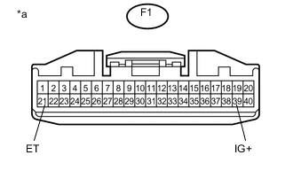
Standard Voltage Tester Connection Switch Condition Specified Condition F1-39 (IG+) - F1-21 (ET) Ignition switch ON 11 to 14 V Table 2. Text in Illustration *a Front view of wire harness connector
(to Combination Meter Assembly)
- OKClick here
- NG
REPAIR OR REPLACE HARNESS OR CONNECTOR
-
- Click here
CHECK SRS WARNING LIGHT
-
Turn the ignition switch off.
-
Disconnect the cable from the negative (-) battery terminal.
CAUTION:Wait at least 90 seconds after disconnecting the cable from the negative (-) battery terminal to disable the SRS system.
-
Connect the connector to the combination meter assembly.
-
Connect the cable to the negative battery terminal, and wait for at least 2 seconds.
-
Turn the ignition switch to ON.
-
Check the SRS warning light condition.
OK The SRS warning light goes off after the primary check period and comes on again after approximately 10 seconds. Tip:The primary check period lasts for approximately 6 seconds after the ignition switch is turned to ON.
- OK
REPLACE AIRBAG SENSOR ASSEMBLY (Click here)
- NG
REPLACE COMBINATION METER ASSEMBLY (Click here)
-