AIRBAG SYSTEM(w/ Curtain Shield Airbag), Diagnostic DTC:B1638/82

| DTC Code | DTC Name |
|---|---|
| B1638/82 | Rear Airbag Sensor Assembly LH Initialization Incomplete |
DESCRIPTION
The side collision sensor LH circuit (to determine deployment of the front seat side airbag assembly LH and curtain shield airbag assembly LH) is composed of the airbag sensor assembly, side airbag sensor assembly LH (for 5 door), door side airbag sensor LH (for 3 door) and No. 2 side airbag sensor assembly LH.
The side airbag sensor assembly LH (for 5 door), door side airbag sensor LH (for 3 door) and No. 2 side airbag sensor assembly LH detect impacts to the vehicle and send signals to the airbag sensor assembly to determine if the airbag should be deployed.
This DTC is stored when a malfunction is detected for the side collision sensor LH circuit (to determine deployment of the front seat side airbag assembly LH and curtain shield airbag assembly LH).
| DTC No. | DTC Detection Condition | Trouble Area |
|---|---|---|
| B1638/82 |
|
|
WIRING DIAGRAM
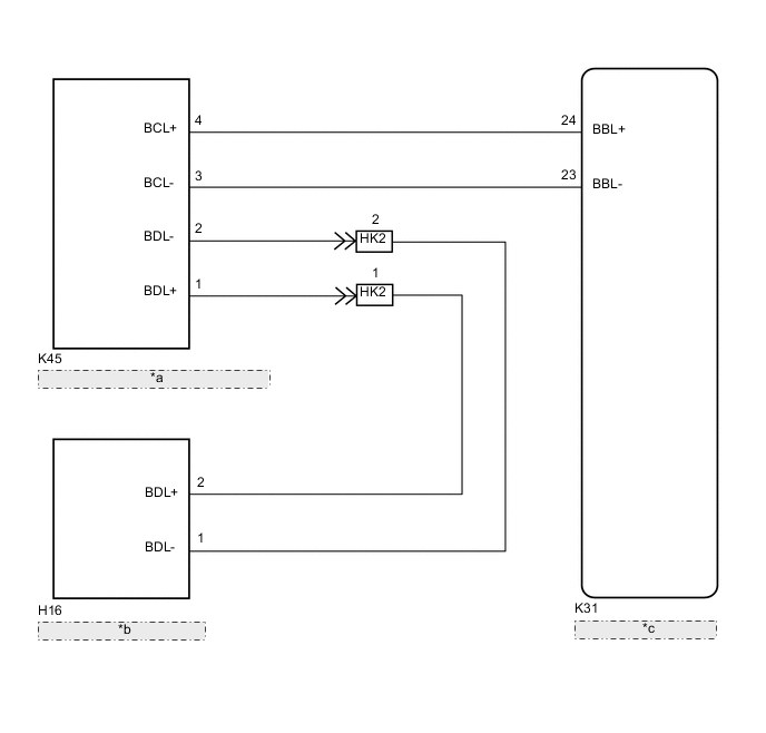
| *a | No. 2 Side Airbag Sensor Assembly LH |
| *b | Door Side Airbag Sensor LH |
| *c | Airbag Sensor Assembly |
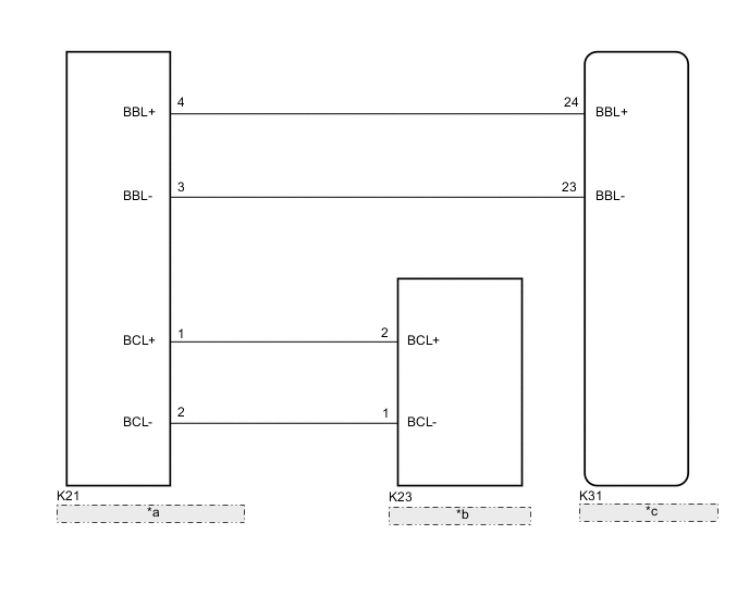
| *a | Side Airbag Sensor Assembly LH |
| *b | No. 2 Side Airbag Sensor Assembly LH |
| *c | Airbag Sensor Assembly |
PROCEDURE
-
SYSTEM CHECK
-
Check the vehicle specifications.
Result Result Proceed to for 3 Door A for 5 Door B
B 
CHECK FLOOR WIRE (OPEN) Click here
A 
-
-
CHECK HISTORY DTC
-
Turn the ignition switch to ON, and wait for at least 60 seconds.
-
Check for history DTCs Click here.
Result History DTC B1632/81 or B1637/82 is not output. Tech Tips
Codes other than history DTCs B1632/81 and B1637/82 may be output at this time, but they are not related to this check.
NG 
INSPECTION PROCEDURE RELEVANT TO OUTPUT DTC Click here
OK
-
-
CHECK CONNECTORS
-
Turn the ignition switch off.
-
Disconnect the cable from the negative (-) battery terminal.
CAUTION:
Wait at least 90 seconds after disconnecting the cable from the negative (-) battery terminal to disable the SRS system.
-
Check that the connectors are properly connected to the airbag sensor assembly, door side airbag sensor LH and No. 2 side airbag sensor assembly LH.
OK The connectors are properly connected. Tech Tips
If the connectors are not connected securely, reconnect the connectors and proceed to the next inspection.
-
Disconnect the connectors from the airbag sensor assembly, door side airbag sensor LH and No. 2 side airbag sensor assembly LH.
-
Check that the terminals of connectors are not damaged.
OK The terminals are not deformed or damaged.
NG
REPLACE WIRE HARNESS
OK
-
-
CHECK FLOOR WIRE (OPEN)
-
Using a service wire, connect terminals 23 (BBL-) and 24 (BBL+) of connector B.
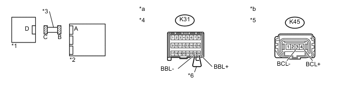
Text in Illustration *1 No. 2 Side Airbag Sensor Assembly LH *2 Airbag Sensor Assembly *3 Floor Wire *4 Connector B *5 Connector C *6 Service Wire *a Front view of wire harness connector
(to Airbag Sensor Assembly)
*b Front view of wire harness connector
(to No. 2 Side Airbag Sensor Assembly LH)
Note
Do not forcibly insert the service wire into the terminals of the connector when connecting.
-
Measure the resistance according to the value(s) in the table below.
Standard Resistance Tester Connection Condition Specified Condition K45-3 (BCL-) - K45-4 (BCL+) Always Below 1 Ω
NG
REPLACE FLOOR WIRE
OK
-
-
CHECK FLOOR WIRE (SHORT)
-
Text in Illustration *1 No. 2 Side Airbag Sensor Assembly LH *2 Airbag Sensor Assembly *3 Floor Wire *4 Connector C *a Front view of wire harness connector
(to No. 2 Side Airbag Sensor Assembly LH)
Disconnect the service wire from connector B.
-
Measure the resistance according to the value(s) in the table below.
Standard Resistance Tester Connection Condition Specified Condition K45-3 (BCL-) - K45-4 (BCL+) Always 1 MΩ or higher
NG
REPLACE FLOOR WIRE
OK
-
-
CHECK FLOOR WIRE (SHORT TO B+)
-
Text in Illustration *1 No. 2 Side Airbag Sensor Assembly LH *2 Airbag Sensor Assembly *3 Floor Wire *4 Connector C *a Front view of wire harness connector
(to No. 2 Side Airbag Sensor Assembly LH)
Connect the cable to the negative (-) battery terminal.
-
Turn the ignition switch to ON.
-
Measure the voltage according to the value(s) in the table below.
Standard Voltage Tester Connection Switch Condition Specified Condition K45-3 (BCL-) - Body ground Ignition switch ON Below 1 V K45-4 (BCL+) - Body ground Ignition switch ON Below 1 V
NG
REPLACE FLOOR WIRE
OK
-
-
CHECK FLOOR WIRE (SHORT TO GROUND)
-
Text in Illustration *1 No. 2 Side Airbag Sensor Assembly LH *2 Airbag Sensor Assembly *3 Floor Wire *4 Connector C *a Front view of wire harness connector
(to No. 2 Side Airbag Sensor Assembly LH)
Turn the ignition switch off.
-
Disconnect the cable from the negative (-) battery terminal.
CAUTION:
Wait at least 90 seconds after disconnecting the cable from the negative (-) battery terminal to disable the SRS system.
-
Measure the resistance according to the value(s) in the table below.
Standard Resistance Tester Connection Condition Specified Condition K45-3 (BCL-) - Body ground Always 1 MΩ or higher K45-4 (BCL+) - Body ground Always 1 MΩ or higher
NG
REPLACE FLOOR WIRE
OK
-
-
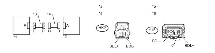
CHECK FLOOR WIRE AND FRONT DOOR WIRE LH (OPEN)
-
Using the service wire, connect terminals 2 (BDL+) and 1 (BDL-) of connector E.
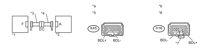
Text in Illustration *1 Door Side Airbag Sensor LH *2 No. 2 Side Airbag Sensor Assembly LH *3 Front Door Wire LH *4 Floor Wire *5 Connector B *6 Connector E *7 Service Wire - - *a Front view of wire harness connector
(to No. 2 Side Airbag Sensor Assembly LH)
*b Front view of wire harness connector
(to Door Side Airbag Sensor LH)
Note
Do not forcibly insert the service wire into the terminals of the connector when connecting.
-
Measure the resistance according to the value(s) in the table below.
Standard Resistance Tester Connection Condition Specified Condition K45-1 (BDL+) - K45-2 (BDL-) Always Below 1 Ω
NG
CHECK FRONT DOOR WIRE LH (OPEN) Click here
OK
-
-
CHECK FLOOR WIRE AND FRONT DOOR WIRE LH (SHORT)
-
Text in Illustration *1 Door Side Airbag Sensor LH *2 No. 2 Side Airbag Sensor Assembly LH *3 Front Door Wire LH *4 Floor Wire *5 Connector B *a Front view of wire harness connector
(to No. 2 Side Airbag Sensor Assembly LH)
Disconnect the service wire from connector E.
-
Measure the resistance according to the value(s) in the table below.
Standard Resistance Tester Connection Condition Specified Condition K45-1 (BDL+) - K45-2 (BDL-) Always 1 MΩ or higher
NG
CHECK FRONT DOOR WIRE LH (SHORT) Click here
OK
-
-
CHECK FLOOR WIRE AND FRONT DOOR WIRE LH (SHORT TO B+)
-
Text in Illustration *1 Door Side Airbag Sensor LH *2 No. 2 Side Airbag Sensor Assembly LH *3 Front Door Wire LH *4 Floor Wire *5 Connector B *a Front view of wire harness connector
(to No. 2 Side Airbag Sensor Assembly LH)
Connect the cable to the negative (-) battery terminal.
-
Turn the ignition switch to ON.
-
Measure the voltage according to the value(s) in the table below.
Standard Voltage Tester Connection Switch Condition Specified Condition K45-1 (BDL+) - Body ground Ignition switch ON Below 1 V K45-2 (BDL-) - Body ground Ignition switch ON Below 1 V
NG
CHECK FRONT DOOR WIRE LH (SHORT TO B+) Click here
OK
-
-
CHECK FLOOR WIRE AND FRONT DOOR WIRE LH (SHORT TO GROUND)
-
Text in Illustration *1 Door Side Airbag Sensor LH *2 No. 2 Side Airbag Sensor Assembly LH *3 Front Door Wire LH *4 Floor Wire *5 Connector B *a Front view of wire harness connector
(to No. 2 Side Airbag Sensor Assembly LH)
Turn the ignition switch off.
-
Disconnect the cable from the negative (-) battery terminal.
CAUTION:
Wait at least 90 seconds after disconnecting the cable from the negative (-) battery terminal to disable the SRS system.
-
Measure the resistance according to the value(s) in the table below.
Standard Resistance Tester Connection Condition Specified Condition K45-1 (BDL+) - Body ground Always 1 MΩ or higher K45-2 (BDL-) - Body ground Always 1 MΩ or higher
NG
CHECK FRONT DOOR WIRE LH (SHORT TO GROUND) Click here
OK
-
-
CHECK NO. 2 SIDE AIRBAG SENSOR ASSEMBLY LH
-
Text in Illustration *1 No. 2 Side Airbag Sensor Assembly RH *2 Airbag Sensor Assembly Connect the connectors to the door side airbag sensor LH and airbag sensor assembly.
-
Interchange the No. 2 side airbag sensor assembly LH with the No. 2 side airbag sensor assembly RH and connect the connectors to them.
-
Connect the cable to the negative (-) battery terminal.
-
Turn the ignition switch to ON, and wait for at least 60 seconds.
-
Clear the DTCs stored in the memory Click here.
-
Turn the ignition switch off.
-
Turn the ignition switch to ON, and wait for at least 60 seconds.
-
Check for DTCs Click here.
Result Result Proceed to DTC B1638/82 is output. A DTC B1633/81 is output. B DTC B1633/81 or B1638/82 is not output. C Tech Tips
Codes other than DTCs B1633/81 and B1638/82 may be output at this time, but they are not related to this check.
-
Turn the ignition switch off.
-
Disconnect the cable from the negative (-) battery terminal.
CAUTION:
Wait at least 90 seconds after disconnecting the cable from the negative (-) battery terminal to disable the SRS system.
-
Return the No. 2 side airbag sensor assembly LH and the No. 2 side airbag sensor assembly RH to their original positions and connect the connectors to them.
B
REPLACE NO. 2 SIDE AIRBAG SENSOR ASSEMBLY LH Click here
C
USE SIMULATION METHOD TO CHECK Click here
A
-
-
CHECK DOOR SIDE AIRBAG SENSOR LH
-
Text in Illustration *1 Door Side Airbag Sensor RH *2 No. 2 Side Airbag Sensor Assembly LH Interchange the door side airbag sensor LH with the door side airbag sensor RH and connect the connectors to them.
-
Connect the cable to the negative (-) battery terminal.
-
Turn the ignition switch to ON, and wait for at least 60 seconds.
-
Clear the DTCs stored in the memory Click here.
-
Turn the ignition switch off.
-
Turn the ignition switch to ON, and wait for at least 60 seconds.
-
Check for DTCs Click here.
Result Result Proceed to DTC B1633/81 or B1638/82 is not output. A DTC B1638/82 is output. B DTC B1633/81 is output. C Tech Tips
Codes other than DTCs B1633/81 and B1638/82 may be output at this time, but they are not related to this check.
-
Turn the ignition switch off.
-
Disconnect the cable from the negative (-) battery terminal.
CAUTION:
Wait at least 90 seconds after disconnecting the cable from the negative (-) battery terminal to disable the SRS system.
-
Return the door side airbag sensor LH and the door side airbag sensor RH to their original positions and connect the connectors to them.
A
USE SIMULATION METHOD TO CHECK Click here
B
REPLACE AIRBAG SENSOR ASSEMBLY Click here
C
REPLACE DOOR SIDE AIRBAG SENSOR LH Click here
-
-
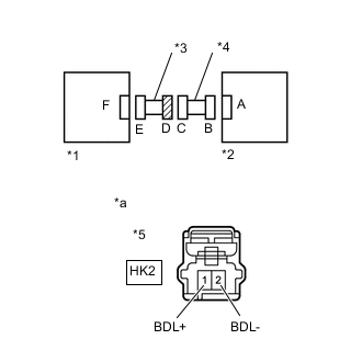
CHECK FRONT DOOR WIRE LH (OPEN)
-
Disconnect the floor wire connector from the front door wire LH.
Text in Illustration *1 Door Side Airbag Sensor LH *2 No. 2 Side Airbag Sensor Assembly LH *3 Front Door Wire LH *4 Floor Wire *5 Connector D *6 Connector E *7 Service Wire - - *a Front view of wire harness connector
(to Floor Wire)
*b Front view of wire harness connector
(to Door Side Airbag Sensor LH)
Tech Tips
The service wire has already been inserted into connector E.
-
Measure the resistance according to the value(s) in the table below.
Standard Resistance Tester Connection Condition Specified Condition HK2-1 (BDL+) - HK2-2 (BDL-) Always Below 1 Ω
OK
REPLACE FLOOR WIRE
NG
REPLACE FRONT DOOR WIRE LH
-
-
CHECK FRONT DOOR WIRE LH (SHORT)
-
Text in Illustration *1 Door Side Airbag Sensor LH *2 No. 2 Side Airbag Sensor Assembly LH *3 Front Door Wire LH *4 Floor Wire *5 Connector D *a Front view of wire harness connector
(to Floor Wire)
Disconnect the floor wire connector from the front door wire LH.
-
Measure the resistance according to the value(s) in the table below.
Standard Resistance Tester Connection Condition Specified Condition HK2-1 (BDL+) - HK2-2 (BDL-) Always 1 MΩ or higher
OK
REPLACE FLOOR WIRE
NG
REPLACE FRONT DOOR WIRE LH
-
-
CHECK FRONT DOOR WIRE LH (SHORT TO B+)
-
Turn the ignition switch off.
-
Text in Illustration *1 Door Side Airbag Sensor LH *2 No. 2 Side Airbag Sensor Assembly LH *3 Front Door Wire LH *4 Floor Wire *5 Connector D *a Front view of wire harness connector
(to Floor Wire)
Disconnect the cable from the negative (-) battery terminal.
CAUTION:
Wait at least 90 seconds after disconnecting the cable from the negative (-) battery terminal to disable the SRS system.
-
Disconnect the front door wire connector from the floor wire.
-
Connect the cable to the negative (-) battery terminal.
-
Turn the ignition switch to ON.
-
Measure the voltage according to the value(s) in the table below.
Standard Voltage Tester Connection Switch Condition Specified Condition HK2-1 (BDL+) - Body ground Ignition switch ON Below 1 V HK2-2 (BDL-) - Body ground Ignition switch ON Below 1 V
OK
REPLACE FLOOR WIRE
NG
REPLACE FRONT DOOR WIRE LH
-
-
CHECK FRONT DOOR WIRE LH (SHORT TO GROUND)
-
Text in Illustration *1 Door Side Airbag Sensor LH *2 No. 2 Side Airbag Sensor Assembly LH *3 Front Door Wire LH *4 Floor Wire *5 Connector D *a Front view of wire harness connector
(to Floor Wire)
Disconnect the front door wire connector from the floor wire.
-
Measure the resistance according to the value(s) in the table below.
Standard Resistance Tester Connection Condition Specified Condition HK2-1 (BDL+) - Body ground Always 1 MΩ or higher HK2-2 (BDL-) - Body ground Always 1 MΩ or higher
OK
REPLACE FLOOR WIRE
NG
REPLACE FRONT DOOR WIRE LH
-
-
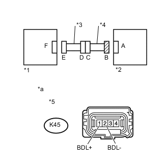
CHECK FLOOR WIRE (OPEN)
-
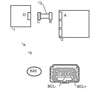
Using a service wire, connect terminals 2 (BCL+) and 1 (BCL-) of connector C.
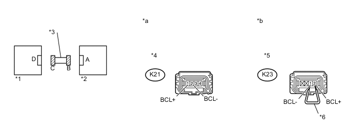
Text in Illustration *1 No. 2 Side Airbag Sensor Assembly LH *2 Side Airbag Sensor Assembly LH *3 Floor Wire *4 Connector B *5 Connector C *6 Service Wire *a Front view of wire harness connector
(to Side Airbag Sensor Assembly LH)
*b Front view of wire harness connector
(to No. 2 Side Airbag Sensor Assembly LH)
Note
Do not forcibly insert the service wire into the terminals of the connector when connecting.
-
Measure the resistance according to the value(s) in the table below.
Standard Resistance Tester Connection Condition Specified Condition K21-1 (BCL+) - K21-2 (BCL-) Always Below 1 Ω
NG
REPLACE FLOOR WIRE
OK
-
-
CHECK FLOOR WIRE (SHORT)
-
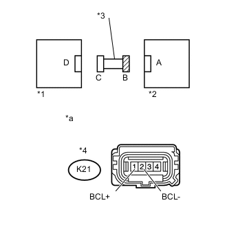
Text in Illustration *1 No. 2 Side Airbag Sensor Assembly LH *2 Side Airbag Sensor Assembly LH *3 Floor Wire *4 Connector B *a Front view of wire harness connector
(to Side Airbag Sensor Assembly LH)
Disconnect the service wire from connector C.
-
Measure the resistance according to the value(s) in the table below.
Standard Resistance Tester Connection Condition Specified Condition K21-1 (BCL+) - K21-2 (BCL-) Always 1 MΩ or higher
NG
REPLACE FLOOR WIRE
OK
-
-
CHECK FLOOR WIRE (SHORT TO B+)
-
Text in Illustration *1 No. 2 Side Airbag Sensor Assembly LH *2 Side Airbag Sensor Assembly LH *3 Floor Wire *4 Connector B *a Front view of wire harness connector
(to Side Airbag Sensor Assembly LH)
Connect the cable to the negative (-) battery terminal.
-
Turn the ignition switch to ON.
-
Measure the voltage according to the value(s) in the table below.
Standard Voltage Tester Connection Switch Condition Specified Condition K21-1 (BCL+) - Body ground Ignition switch ON Below 1 V K21-2 (BCL-) - Body ground Ignition switch ON Below 1 V
NG
REPLACE FLOOR WIRE
OK
-
-
CHECK FLOOR WIRE (SHORT TO GROUND)
-
Text in Illustration *1 No. 2 Side Airbag Sensor Assembly LH *2 Side Airbag Sensor Assembly LH *3 Floor Wire *4 Connector B *a Front view of wire harness connector
(to Side Airbag Sensor Assembly LH)
Turn the ignition switch off.
-
Disconnect the cable from the negative (-) battery terminal.
CAUTION:
Wait at least 90 seconds after disconnecting the cable from the negative (-) battery terminal to disable the SRS system.
-
Measure the resistance according to the value(s) in the table below.
Standard Resistance Tester Connection Condition Specified Condition K21-1 (BCL+) - Body ground Always 1 MΩ or higher K21-2 (BCL-) - Body ground Always 1 MΩ or higher
NG
REPLACE FLOOR WIRE
OK
-
-
CHECK SIDE AIRBAG SENSOR ASSEMBLY LH
-
Text in Illustration *1 Side Airbag Sensor Assembly RH *2 Airbag Sensor Assembly Connect the connectors to the No. 2 side airbag sensor assembly LH and airbag sensor assembly.
-
Interchange the side airbag sensor assembly LH with the side airbag sensor assembly RH and connect the connectors to them.
-
Connect the cable to the negative (-) battery terminal.
-
Turn the ignition switch to ON, and wait for at least 60 seconds.
-
Clear the DTCs stored in the memory Click here.
-
Turn the ignition switch off.
-
Turn the ignition switch to ON, and wait for at least 60 seconds.
-
Check for DTCs Click here.
Result Result Proceed to DTC B1638/82 is output. A DTC B1633/81 is output. B DTC B1633/81 or B1638/82 is not output. C Tech Tips
Codes other than DTCs B1633/81 and B1638/82 may be output at this time, but they are not related to this check.
-
Turn the ignition switch off.
-
Disconnect the cable from the negative (-) battery terminal.
CAUTION:
Wait at least 90 seconds after disconnecting the cable from the negative (-) battery terminal to disable the SRS system.
-
Return the side airbag sensor assembly LH and the side airbag sensor assembly RH to their original positions and connect the connectors to them.
B
REPLACE SIDE AIRBAG SENSOR ASSEMBLY LH Click here
C
USE SIMULATION METHOD TO CHECK Click here
A
-
-
CHECK NO. 2 SIDE AIRBAG SENSOR ASSEMBLY LH
-
Text in Illustration *1 No. 2 Side Airbag Sensor Assembly RH *2 Side Airbag Sensor Assembly LH Interchange the No. 2 side airbag sensor assembly LH with the No. 2 side airbag sensor assembly RH and connect the connectors to them.
-
Connect the cable to the negative (-) battery terminal.
-
Turn the ignition switch to ON, and wait for at least 60 seconds.
-
Clear the DTCs stored in the memory Click here.
-
Turn the ignition switch off.
-
Turn the ignition switch to ON, and wait for at least 60 seconds.
-
Check for DTCs Click here.
Result Result Proceed to DTC B1633/81 or B1638/82 is not output. A DTC B1638/82 is output. B DTC B1633/81 is output. C Tech Tips
Codes other than DTCs B1633/81 and B1638/82 may be output at this time, but they are not related to this check.
-
Turn the ignition switch off.
-
Disconnect the cable from the negative (-) battery terminal.
CAUTION:
Wait at least 90 seconds after disconnecting the cable from the negative (-) battery terminal to disable the SRS system.
-
Return the No. 2 side airbag sensor assembly LH and the No. 2 side airbag sensor assembly RH to their original positions and connect the connectors to them.
A
USE SIMULATION METHOD TO CHECK Click here
B
REPLACE AIRBAG SENSOR ASSEMBLY Click here
C
REPLACE NO. 2 SIDE AIRBAG SENSOR ASSEMBLY LH Click here
-