METER / GAUGE SYSTEM Engine Coolant Temperature Receiver Gauge Malfunction
DESCRIPTION
In this circuit, the combination meter assembly receives engine coolant temperature signals from the ECM using the CAN communication line. The combination meter assembly displays the engine coolant temperature, which is calculated based on the data received from the ECM.
WIRING DIAGRAM
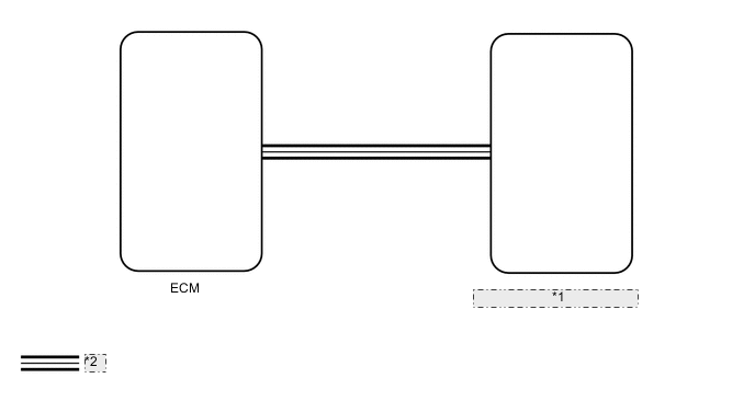
| *1 | Combination Meter Assembly |
| *2 | CAN Communication Line |
CAUTION / NOTICE / HINT
Note
When replacing the combination meter assembly, make sure to replace it with a new one. If a combination meter assembly which was installed to another vehicle is used, the information stored in it will not match the information from the vehicle and a DTC may be stored.
PROCEDURE
-
CHECK FOR DTC
-
Check for DTCs.
OK DTCs U0100, U0129, U0131, U0142, U0151, U0163 and U023A are not output. Result Result Proceed to CAN communication DTC is not output A DTC is output (w/o Toyota Safety Sense) B DTC is output (w/ Toyota Safety Sense) C
B 
GO TO CAN COMMUNICATION SYSTEM Click here
C
GO TO CAN COMMUNICATION SYSTEM Click here
A 
-
-
CHECK VEHICLE TYPE
-
Check the vehicle type.
Result Result Proceed to except 2ZR-FE A for 2ZR-FE B
B 
CHECK ENGINE CONTROL SYSTEM Click here
A
-
-
CHECK ENGINE CONTROL SYSTEM
-
Check if an engine control DTC is output.
-
for 2NR-FKE: Click here
-
for 1KR-FE: Click here
-
for 1ND-TV with DPF: Click here
-
for 1ND-TV without DPF: Click here
OK DTC is not output. Result Result Proceed to Engine control DTC is not output A Engine control DTC is output (for 2NR-FKE) B Engine control DTC is output (for 1KR-FE) C Engine control DTC is output (for 1ND-TV with DPF) D Engine control DTC is output (for 1ND-TV without DPF) E -
B
GO TO SFI SYSTEM Click here
C
GO TO SFI SYSTEM Click here
D
GO TO ECD SYSTEM Click here
E
GO TO ECD SYSTEM Click here
A
-
-
PERFORM ACTIVE TEST USING GTS (WATER TEMPERATURE METER OPERATION)
-
Connect the GTS to the DLC3.
-
Turn the ignition switch to ON.
-
Turn the GTS on.
-
Enter the following menus: Body / Combination Meter / Active Test.
-
According to the display on the GTS, perform the Active Test.
Body Electrical > Combination Meter > Active Test Tester Display Measurement Item Control Range Diagnostic Note Water Temperature Meter Operation Engine coolant temperature receiver gauge OFF, LOW, NORMAL or HIGH - OK Engine coolant temperature receiver gauge indication is normal.
NG
REPLACE COMBINATION METER ASSEMBLY Click here
OK
-
-
READ VALUE USING GTS (COOLANT TEMPERATURE, COOLANT TEMP)
-
Connect the GTS to the DLC3.
-
Turn the ignition switch to ON.
-
Turn the GTS on.
-
Enter the following menus:
-
Body Electrical / Combination Meter / Data List
-
Powertrain / Engine and ECT / Data List
-
-
According to the display on the GTS, read the Data List.
Combination Meter Tester Display Measurement Item Control Range Normal Condition Diagnostic Note Coolant Temperature Engine coolant temperature 0 to 127.5°C (0 to 261.5°F) After warming up: 80 to 100°C (176 to 212°F) - Engine and ECT Tester Display Measurement Item Control Range Normal Condition Diagnostic Note Coolant Temp Engine coolant temperature Min.: -40°C (-40°F), Max: 215°C (419°F) After warming up engine: 60 to 90°C (140 to 194°F) - Tech Tips
-
When the Data List values of the ECUs match, an internal malfunction of the ECM is suspected.
-
When the Data List values of the ECUs do not match, a signal output error of the ECM or an internal malfunction of the combination meter assembly is suspected.
Result Result Proceed to The Data List values of the ECUs do not match. A The Data List values of the ECUs match. B -
A
REPLACE COMBINATION METER ASSEMBLY Click here
B
-
-
CHECK COMBINATION METER ASSEMBLY
-
Replace the combination meter assembly with a new one.
-
Check that the operation of the engine coolant temperature receiver gauge returns to normal.
OK The operation of the engine coolant temperature receiver gauge returns to normal. Result Result Result OK A NG (for 2NR-FKE) B NG (for 1KR-FE) C NG (for 1ND-TV with DPF) D NG (for 1ND-TV without DPF) E
A
END (COMBINATION METER ASSEMBLY WAS DEFECTIVE)
B
REPLACE ECM Click here
C
REPLACE ECM Click here
D
REPLACE ECM Click here
E
REPLACE ECM Click here
-
-
CHECK ENGINE CONTROL SYSTEM
-
Check if an engine control DTC is output.
OK DTC is not output.
NG
GO TO SFI SYSTEM Click here
OK
-
-
PERFORM ACTIVE TEST USING GTS (WATER TEMPERATURE METER OPERATION)
-
Connect the GTS to the DLC3.
-
Turn the ignition switch to ON.
-
Turn the GTS on.
-
Enter the following menus: Body / Combination Meter / Active Test.
-
According to the display on the GTS, perform the Active Test.
Body Electrical > Combination Meter > Active Test Tester Display Measurement Item Control Range Diagnostic Note Water Temperature Meter Operation Engine coolant temperature receiver gauge OFF, LOW, NORMAL or HIGH - OK Engine coolant temperature receiver gauge indication is normal.
NG
REPLACE COMBINATION METER ASSEMBLY Click here
OK
-
-
READ VALUE USING GTS (COOLANT TEMPERATURE, COOLANT TEMP)
-
Connect the GTS to the DLC3.
-
Turn the ignition switch to ON.
-
Turn the GTS on.
-
Enter the following menus:
-
Body Electrical / Combination Meter / Data List
-
Powertrain / Engine and ECT / Data List
-
-
According to the display on the GTS, read the Data List.
Combination Meter Tester Display Measurement Item Control Range Normal Condition Diagnostic Note Coolant Temperature Engine coolant temperature 0 to 127.5°C (0 to 261.5°F) After warming up: 80 to 100°C (176 to 212°F) - Engine and ECT Tester Display Measurement Item Control Range Normal Condition Diagnostic Note Coolant Temp Engine coolant temperature Min.: -40°C (-40°F), Max: 215°C (419°F) After warming up engine: 60 to 90°C (140 to 194°F) - Tech Tips
-
When the Data List values of the ECUs match, an internal malfunction of the ECM is suspected.
-
When the Data List values of the ECUs do not match, a signal output error of the ECM or an internal malfunction of the combination meter assembly is suspected.
Result Result Proceed to The Data List values of the ECUs do not match. A The Data List values of the ECUs match. B -
A
REPLACE COMBINATION METER ASSEMBLY Click here
B
-
-
CHECK COMBINATION METER ASSEMBLY
OK
END (COMBINATION METER ASSEMBLY WAS DEFECTIVE)
NG
REPLACE ECM Click here