METER / GAUGE SYSTEM Fuel Receiver Gauge Malfunction
DESCRIPTION
-
The combination meter assembly controls the fuel receiver gauge in accordance with the resistance of the fuel sender gauge assembly, which varies depending on the amount of fuel remaining in the fuel tank.
WIRING DIAGRAM
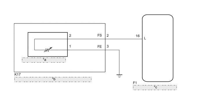
| *a | Fuel Sender Gauge Assembly |
| *b | Fuel Suction with Pump and Gauge Tube Assembly |
| *c | Combination Meter Assembly |
PROCEDURE
-
CONFIRM DTC OUTPUT
-
Check DTC Click here.
Result Result Proceed to DTC B1500 is not output A DTC B1500 is output B
B 
GO TO DIAGNOSTIC TROUBLE CODE CHART Click here
A 
-
-
PERFORM ACTIVE TEST USING INTELLIGENT TESTER (FUEL METER OPERATION)
-
Connect the intelligent tester to the DLC3.
-
Turn the ignition switch to ON.
-
Turn the intelligent tester on.
-
Enter the following menus: Body / Combination Meter / Active Test.
-
According to the display on the intelligent tester, perform the Active Test.
Combination Meter Tester Display Test Part Control Range Diagnostic Note Fuel Meter Operation Fuel gauge EMPTY/ 1/2 /FULL Vehicle is stopped and the engine idling. OK Fuel receiver gauge indication is normal.
NG
REPLACE COMBINATION METER ASSEMBLY Click here
OK
-
-
INSPECT FUEL SENDER GAUGE ASSEMBLY
-
Remove the fuel sender gauge assembly.
-
for 1NR-FE Click here
-
for 1KR-FE Click here
-
for 1ND-TV Click here
-
-
for 1NR-FE and 1KR-FE:
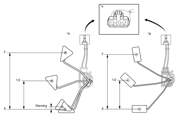
Text in Illustration *A Fuel Sender Gauge Assembly (Type A) *B Fuel Sender Gauge Assembly (Type B) *a Component without harness connected
(Fuel Sender Gauge Assembly)
- -
-
Check that the float moves smoothly between F and E.
-
Measure the resistance according to the value(s) in the table below.
Standard Resistance Tester Connection Float Level Float Position (mm (in.)) Specified Condition Fuel Sender Gauge Assembly ( Type A) Fuel Sender Gauge Assembly ( Type B) Fuel Sender Gauge Assembly ( Type A) Fuel Sender Gauge Assembly ( Type B) 1 - 2 F 142 to 152 (5.591 to 5.984) 134.3 to 146.3 (5.287 to 5.760) 12.0 to 18.0 Ω 13.5 to 16.5 Ω 1/2 71.1 to 76.1 (2.799 to 2.996) 67.4 to 79.4 (2.654 to 3.126) 202.2 to 214.3 Ω 196.4 to 220.0 Ω Warning 5.9 to 10.9 (0.232 to 0.429) - 359.7 to 388.2 Ω - E 0 (0) 0 (0) 405.0 to 415.0 Ω 405.5 to 414.5 Ω
-
-
for 1ND-TV:
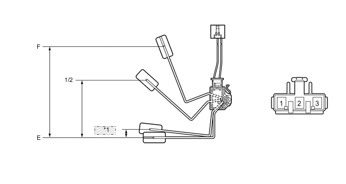
*1 Warning Text in Illustration *a Component without harness connected
(Fuel Sender Gauge Assembly)
- -
-
Check that the float moves smoothly between F and E.
-
Measure the resistance according to the value(s) in the table below.
Standard Resistance Tester Connection Float Level Float Position (mm (in.)) Specified Condition 1 - 2 F 148.3 to 156.3 (5.839 to 6.154) 12.0 to 18.0 Ω 1/2 82.5 to 86.5 (3.248 to 3.406) 202.2 to 214.3 Ω Warning 17.2 to 21.2 (0.677 to 0.835) 359.7 to 388.2 Ω E 0 (0) 405.0 to 415.0 Ω Result Result Proceed to OK A NG (for 1NR-FE) B NG (for 1KR-FE) C NG (for 1ND-TV) D
-
-
Reinstall the fuel sender gauge assembly.
-
for 1NR-FE Click here
-
for 1KR-FE Click here
-
for 1ND-TV Click here
-
B
REPLACE FUEL SENDER GAUGE ASSEMBLY Click here
C
REPLACE FUEL SENDER GAUGE ASSEMBLY Click here
D
REPLACE FUEL SENDER GAUGE ASSEMBLY Click here
A
-
-
CHECK FUEL SUCTION WITH PUMP AND GAUGE TUBE ASSEMBLY
-
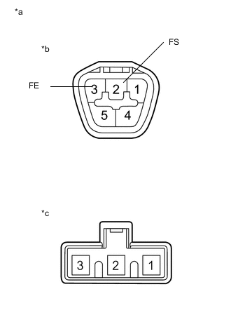
Text in Illustration *a Component without harness connected
(Fuel Suction with Pump and Gauge Tube Assembly)
*b Connector A *c Connector B Remove the fuel suction with pump and gauge tube assembly.
-
for 1NR-FE Click here
-
for 1KR-FE Click here
-
for 1ND-TV Click here
-
-
Measure the resistance according to the value(s) in the table below.
Standard Resistance Tester Connection Condition Specified Condition A-2 (FS) - B-2 Always Below 1 Ω A-3 (FE) - B-1 Always Below 1 Ω Result Result Proceed to OK A NG (for 1NR-FE) B NG (for 1KR-FE) C NG (for 1ND-TV) D -
Reinstall the fuel suction plate sub-assembly.
-
for 1NR-FE Click here
-
for 1KR-FE Click here
-
for 1ND-TV Click here
-
B
REPLACE FUEL SUCTION WITH PUMP AND GAUGE TUBE ASSEMBLY Click here
C
REPLACE FUEL SUCTION WITH PUMP AND GAUGE TUBE ASSEMBLY Click here
D
REPLACE FUEL SUCTION WITH PUMP AND GAUGE TUBE ASSEMBLY Click here
A
-
-
CHECK HARNESS AND CONNECTOR (COMBINATION METER ASSEMBLY - FUEL SUCTION WITH PUMP AND GAUGE TUBE ASSEMBLY)
-
Disconnect the F1 combination meter assembly connector.
-
Disconnect the K17 fuel suction with pump and gauge tube assembly connector.
-
Measure the resistance according to the value(s) in the table below.
Standard Resistance Tester Connection Condition Specified Condition F1-16 (L) - K17-2 (FS) Always Below 1 Ω F1-16 (L) - Body ground Always 10 kΩ or higher K17-3 (FE) - Body ground Always Below 1 Ω -
Reconnect the fuel suction with pump and gauge tube assembly connector.
-
Reconnect the combination meter assembly connector.
OK
REPLACE COMBINATION METER ASSEMBLY Click here
NG
REPAIR OR REPLACE HARNESS OR CONNECTOR
-