METER / GAUGE SYSTEM Tachometer Malfunction
DESCRIPTION
In this circuit, the meter CPU receives engine speed signals from the ECM using the CAN communication system. The meter CPU displays the engine speed calculated based on the data received from the ECM.
WIRING DIAGRAM
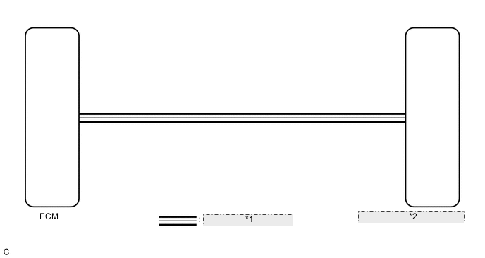
| *1 | CAN Communication Line |
| *2 | Combination Meter Assembly |
PROCEDURE
-
CHECK CAN COMMUNICATION SYSTEM
-
Check if a CAN communication system DTC is output.
-
w/o Toyota Safety Sense Click here
-
w/ Toyota Safety Sense Click here
Result Result Proceed to CAN communication DTC is not output A DTC is output (w/o Toyota Safety Sense) B DTC is output (w/ Toyota Safety Sense) C -
B 
GO TO CAN COMMUNICATION SYSTEM Click here
C
GO TO CAN COMMUNICATION SYSTEM Click here
A 
-
-
PERFORM ACTIVE TEST USING GTS (TACHOMETER OPERATION)
-
Connect the GTS to the DLC3.
-
Turn the ignition switch to ON.
-
Turn the GTS on.
-
Enter the following menus: Body / Combination Meter / Active Test.
-
According to the display on the GTS, perform the Active Test.
Combination Meter Tester Display Test Part Control Range Diagnostic Note TachoMeter Operation Tachometer 0/1000/2000/3000/4000/5000/6000/7000 rpm Perform the test with the vehicle stopped and the engine idling. OK Tachometer indication is normal.
NG
REPLACE COMBINATION METER ASSEMBLY Click here
OK
-
-
READ VALUE USING GTS (ENGINE RPM)
-
Connect the GTS to the DLC3.
-
Start the engine.
-
Turn the GTS on.
-
Enter the following menus: Body / Combination Meter / Data List.
-
According to the display on the GTS, read the Data List.
Combination Meter Tester Display Measurement Item/Range Normal Condition Diagnostic Note Engine Rpm Engine speed/
Min.: 0
Max.: 12750
Approximately same as actual engine speed (when engine is running) Unit: rpm OK Engine speed displayed on the GTS is almost the same as the tachometer indication. Tech Tips
Check the engine speed when the engine is fully warmed up, and the air conditioning and all electrical accessories are off.
NG
REPLACE COMBINATION METER ASSEMBLY Click here
OK
-
-
CHECK ENGINE CONTROL SYSTEM
-
Check if an engine control DTC is output.
-
for 2NR-FKE Click here
-
for 1KR-FE Click here
-
for 1ND-TV with DPF Click here
-
for 1ND-TV without DPF Click here
Result Result Proceed to Engine control DTC is not output A Engine control DTC is output (for 2NR-FKE) B Engine control DTC is output (for 1KR-FE) C Engine control DTC is output (for 1ND-TV with DPF) D Engine control DTC is output (for 1ND-TV without DPF) E -
A
REPLACE COMBINATION METER ASSEMBLY Click here
B
GO TO SFI SYSTEM Click here
C
GO TO SFI SYSTEM Click here
D
GO TO ECD SYSTEM Click here
E
GO TO ECD SYSTEM Click here
-