METER / GAUGE SYSTEM, Diagnostic DTC:B1500
| DTC Code | DTC Name |
|---|---|
| B1500 | Fuel Sender Open Detected |
DESCRIPTION
This DTC is output when the combination meter assembly detects a fuel sender gauge assembly malfunction.
| DTC No. | DTC Detection Condition | Trouble Area |
|---|---|---|
| B1500 | When combination meter detects fuel sender gauge malfunction |
|
-
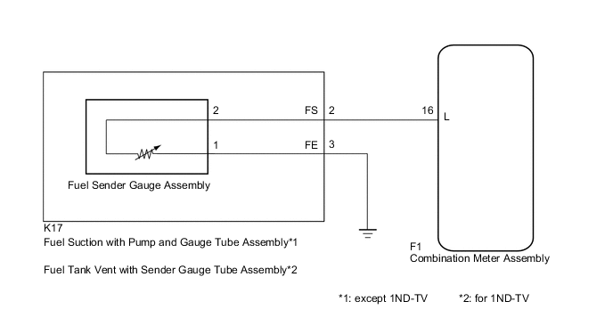
*1: except 1ND-TV
-
*2: for 1ND-TV
WIRING DIAGRAM
CAUTION / NOTICE / HINT
Note
When replacing the combination meter assembly, always replace it with a new one. If a combination meter assembly which was installed to another vehicle is used, the information stored in it will not match the information from the vehicle and a DTC may be stored.
PROCEDURE
-
INSPECT FUEL SENDER GAUGE ASSEMBLY
-
Remove the fuel sender gauge assembly.
-
for 2NR-FKE Click here
-
for 1KR-FE Click here
-
for 2ZR-FE Click here
-
for 1ND-TV Click here
-
-
Inspect the fuel sender gauge assembly.
-
for 2NR-FKE Click here
-
for 1KR-FE Click here
-
for 2ZR-FE Click here
-
for 1ND-TV Click here
-
-
Reinstall the fuel sender gauge assembly.
-
for 2NR-FKE Click here
-
for 1KR-FE Click here
-
for 2ZR-FE Click here
-
for 1ND-TV Click here
Result Result Proceed to OK A NG (for 2NR-FKE) B NG (for 1KR-FE) C NG (for 2ZR-FE) D NG (for 1ND-TV) E -
B 
REPLACE FUEL SENDER GAUGE ASSEMBLY Click here
C
REPLACE FUEL SENDER GAUGE ASSEMBLY Click here
D
REPLACE FUEL SENDER GAUGE ASSEMBLY Click here
E
REPLACE FUEL SENDER GAGE ASSEMBLY Click here
A 
-
-
SYSTEM CHECK
-
Check the vehicle specifications.
Result Result Proceed to except 1ND-TV A for 1ND-TV B
B 
INSPECT FUEL TANK VENT WITH SENDER GAUGE TUBE ASSEMBLY Click here
A
-
-
INSPECT FUEL SUCTION WITH PUMP AND GAUGE TUBE ASSEMBLY
-

Text in Illustration *a Component without harness connected
(Fuel Suction with Pump and Gauge Tube Assembly)
*b Connector A *c Connector B Remove the fuel suction with pump and gauge tube assembly.
-
for 2NR-FKE Click here
-
for 1KR-FE Click here
-
for 2ZR-FE Click here
-
-
Measure the resistance according to the value(s) in the table below.
Standard Resistance Tester Connection Condition Specified Condition A-2 (FS) - B-2 Always Below 1 Ω A-3 (FE) - B-1 Always Below 1 Ω Result Result Proceed to OK A NG (for 2NR-FKE) B NG (for 1KR-FE) C NG (for 2ZR-FE) D -
Reinstall the fuel suction with pump and gauge tube assembly.
-
for 2NR-FKE Click here
-
for 1KR-FE Click here
-
for 2ZR-FE Click here
-
B
REPLACE CHARCOAL CANISTER SUB-ASSEMBLY Click here
C
REPLACE CHARCOAL CANISTER SUB-ASSEMBLY Click here
D
REPLACE CHARCOAL CANISTER SUB-ASSEMBLY Click here
A
-
-
CHECK HARNESS AND CONNECTOR (COMBINATION METER ASSEMBLY - FUEL SUCTION WITH PUMP AND GAUGE TUBE ASSEMBLY)
-
Disconnect the F1 combination meter assembly connector.
-
Disconnect the K17 fuel suction with pump and gauge tube assembly connector.
-
Measure the resistance according to the value(s) in the table below.
Standard Resistance Tester Connection Condition Specified Condition F1-16 (L) - K17-2 (FS) Always Below 1 Ω F1-16 (L) - Body ground Always 10 kΩ or higher K17-3 (FE) - Body ground Always Below 1 Ω -
Reconnect the fuel suction with pump and gauge tube assembly connector.
-
Reconnect the combination meter assembly connector.
OK
REPLACE COMBINATION METER ASSEMBLY Click here
NG
REPAIR OR REPLACE HARNESS OR CONNECTOR
-
-
INSPECT FUEL TANK VENT WITH SENDER GAUGE TUBE ASSEMBLY
-
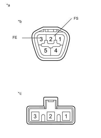
Text in Illustration *a Component without harness connected
(Fuel Tank Vent with Sender Gauge Tube Assembly)
*b Connector A *c Connector B Remove the fuel tank vent with sender gauge tube assembly Click here.
-
Measure the resistance according to the value(s) in the table below.
Standard Resistance Tester Connection Condition Specified Condition A-2 (FS) - B-2 Always Below 1 Ω A-3 (FE) - B-1 Always Below 1 Ω -
Reinstall the fuel tank vent with sender gauge tube assembly Click here.
NG
REPLACE FUEL TANK VENT WITH SENDER GAUGE TUBE ASSEMBLY Click here
OK
-
-
CHECK HARNESS AND CONNECTOR (COMBINATION METER ASSEMBLY - FUEL TANK VENT WITH SENDER GAUGE TUBE ASSEMBLY)
-
Disconnect the F1 combination meter assembly connector.
-
Disconnect the K17 fuel tank vent with sender gauge tube assembly connector.
-
Measure the resistance according to the value(s) in the table below.
Standard Resistance Tester Connection Condition Specified Condition F1-16 (L) - K17-2 (FS) Always Below 1 Ω F1-16 (L) - Body ground Always 10 kΩ or higher K17-3 (FE) - Body ground Always Below 1 Ω -
Reconnect the fuel tank vent with sender gauge tube assembly connector.
-
Reconnect the combination meter assembly connector.
OK
REPLACE COMBINATION METER ASSEMBLY Click here
NG
REPAIR OR REPLACE HARNESS OR CONNECTOR
-