METER / GAUGE SYSTEM, Diagnostic DTC:B1500
| DTC Code | DTC Name |
|---|---|
| B1500 | Fuel Sender Open Detected |
DESCRIPTION
This DTC is output when the combination meter assembly detects a fuel sender gauge malfunction.
| DTC No. | DTC Detection Condition | Trouble Area |
|---|---|---|
| B1500 | When combination meter detects fuel sender gauge malfunction |
|
WIRING DIAGRAM
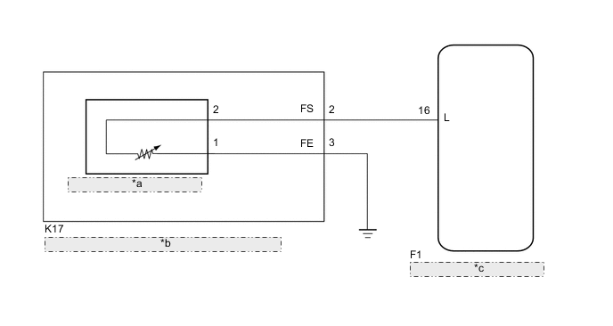
| *a | Fuel Sender Gauge Assembly |
| *b | Fuel Suction with Pump and Gauge Tube Assembly |
| *c | Combination Meter Assembly |
PROCEDURE
-
PERFORM ACTIVE TEST USING INTELLIGENT TESTER (FUEL METER OPERATION)
-
Connect the intelligent tester to the DLC3.
-
Turn the ignition switch to ON.
-
Turn the intelligent tester on.
-
Enter the following menus: Body / Combination Meter / Active Test.
-
According to the display on the intelligent tester, perform the Active Test.
Combination Meter Tester Display Test part Control Range Diagnostic Note Fuel Meter Operation Fuel gauge EMPTY / 1/2 / FULL Vehicle is stopped and the engine idling OK Fuel receiver gauge indication is normal.
NG 
REPLACE COMBINATION METER ASSEMBLY Click here
OK 
-
-
READ VALUE USING INTELLIGENT TESTER (FUEL INPUT)
-
Connect the intelligent tester to the DLC3.
-
Turn the ignition switch to ON.
-
Turn the intelligent tester on.
-
Enter the following menus: Body / Combination Meter / Data List.
-
According to the display on the intelligent tester, read the Data List.
Combination Meter Tester Display Measurement Item/Range Normal Condition Diagnostic Note Fuel Input Fuel sender gauge input/
Min.: 0
Max.: 127.5
Fuel sender input value Unit: Liter OK Fuel value displayed on the tester is approximately the same as needle indication.
OK
REPLACE COMBINATION METER ASSEMBLY Click here
NG
-
-
INSPECT FUEL SENDER GAUGE ASSEMBLY
-
Remove the fuel sender gauge assembly.
-
for 1NR-FE Click here
-
for 1KR-FE Click here
-
for 1ND-TV Click here
-
-
for 1NR-FE and 1KR-FE:
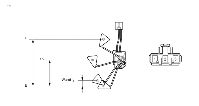
Text in Illustration *a Component without harness connected
(Fuel Sender Gauge Assembly)
- -
-
Check that the float moves smoothly between F and E.
-
Measure the resistance according to the value(s) in the table below.
Standard Resistance Tester Connection Float Level Float Position (mm (in.)) Specified Condition 1 - 2 F 142 to 152 (5.591 to 5.984) 12.0 to 18.0 Ω 1/2 71.1 to 76.1 (2.799 to 2.996) 208.3 Ω Warning 5.9 to 10.9 (0.232 to 0.429) 365.2 Ω E 0 (0) 405.0 to 415.0 Ω
-
-
for 1ND-TV:
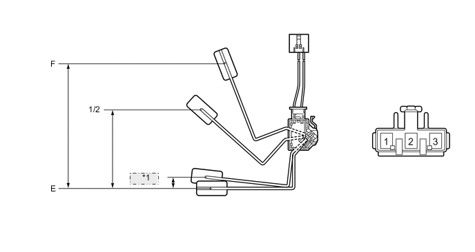
*1 Warning Text in Illustration *a Component without harness connected
(Fuel Sender Gauge Assembly)
- -
-
Check that the float moves smoothly between F and E.
-
Measure the resistance according to the value(s) in the table below.
Standard Resistance Tester Connection Float Level Float Position (mm (in.)) Specified Condition 1 - 2 F 148.3 to 156.3 (5.839 to 6.154) 12.0 to 18.0 Ω 1/2 82.5 to 86.5 (3.248 to 3.406) 208.3 Ω Warning 17.2 to 21.2 (0.677 to 0.835) 365.2 Ω E 0 (0) 405.0 to 415.0 Ω Result Result Proceed to OK A NG (for 1NR-FE) B NG (for 1KR-FE) C NG (for 1ND-TV) D
-
-
Reinstall the fuel sender gauge assembly.
B
REPLACE FUEL SENDER GAUGE ASSEMBLY Click here
C
REPLACE FUEL SENDER GAUGE ASSEMBLY Click here
D
REPLACE FUEL SENDER GAUGE ASSEMBLY Click here
A
-
-
INSPECT FUEL SUCTION WITH PUMP AND GAUGE TUBE ASSEMBLY
-
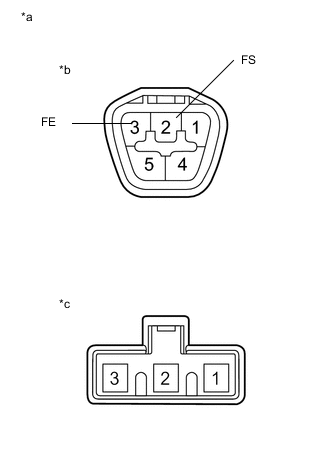
Text in Illustration *a Component without harness connected
(Fuel Suction with Pump and Gauge Tube Assembly)
*b Connector A *c Connector B Remove the fuel suction with pump and gauge tube assembly.
-
for 1NR-FE Click here
-
for 1KR-FE Click here
-
for 1ND-TV Click here
-
-
Measure the resistance according to the value(s) in the table below.
Standard Resistance Tester Connection Condition Specified Condition A-2 (FS) - B-2 Always Below 1 Ω A-3 (FE) - B-1 Always Below 1 Ω Result Result Proceed to OK A NG (for 1NR-FE) B NG (for 1KR-FE) C NG (for 1ND-TV) D -
Reinstall the fuel suction plate sub-assembly.
B
REPLACE FUEL SUCTION WITH PUMP AND GAUGE TUBE ASSEMBLY Click here
C
REPLACE FUEL SUCTION WITH PUMP AND GAUGE TUBE ASSEMBLY Click here
D
REPLACE FUEL SUCTION WITH PUMP AND GAUGE TUBE ASSEMBLY Click here
A
-
-
CHECK HARNESS AND CONNECTOR (COMBINATION METER ASSEMBLY - FUEL SUCTION W/PUMP AND GAUGE TUBE ASSEMBLY)
-
Disconnect the F1 combination meter assembly connector.
-
Disconnect the K17 fuel suction with pump and gauge tube assembly connector.
-
Measure the resistance according to the value(s) in the table below.
Standard Resistance Tester Connection Condition Specified Condition F1-16 (L) - K17-2 (FS) Always Below 1 Ω F1-16 (L) - Body ground Always 10 kΩ or higher K17-3 (FE) - Body ground Always Below 1 Ω -
Reconnect the fuel suction with pump and gauge tube assembly connector.
-
Reconnect the combination meter assembly connector.
OK
REPLACE COMBINATION METER ASSEMBLY Click here
NG
REPAIR OR REPLACE HARNESS OR CONNECTOR
-