METER / GAUGE SYSTEM TERMINALS OF ECU
-
CHECK COMBINATION METER ASSEMBLY
-
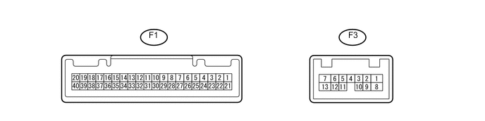
Disconnect the F1 and F3 combination meter assembly connector.
-
Measure the voltage, resistance and check for pulses of the wire harness side connector.
Terminals No. (Symbol) Wiring Color Terminal Description Condition Specified Condition F1-21 (ET) - Body ground W-B - Body ground Ground Always Below 1 Ω F1-39 (IG+) - Body ground P - Body ground Ignition switch signal Ignition switch off → ON Below 1 V → 11 to 14 V F1-40 (B) - Body ground L - Body ground Battery Always 11 to 14 V F3-1 (B) - Body ground R - Body ground Battery Always 11 to 14 V If the result is not as specified, there may be a malfunction in the wire harness.
-
Reconnect the F1 and F3 combination meter assembly connector.
-
Measure the voltage, resistance and check for pulses of the wire harness side connector.
Terminals No. (Symbol) Wiring Color Terminal Description Condition Specified Condition F1-1 (RLMT)*2 - Body ground GR - Body ground Rear LH seat belt warning light signal Rear LH seat belt warning light ON → OFF Below 1 V → 11 to 14 V F1-2 (RCMT)*2 - Body ground G - Body ground Rear CENTER seat belt warning light signal Rear CENTER seat belt warning light ON → OFF Below 1 V → 11 to 14 V F1-3 (RRMT)*2 - Body ground B - Body ground Rear RH seat belt warning light signal Rear RH seat belt warning light ON → OFF Below 1 V → 11 to 14 V F1-5 (SI) - Body ground L - Body ground Speed signal (Input) Driving at approximately
20 km/h (12 mph)
Pulse generation
(See waveform 1)
F1-6 (+S) - Body ground SB - Body ground Speed signal (Output) Driving at approximately
20 km/h (12 mph)
Pulse generation
(See waveform 1)
F1-7 (P/SB) - Body ground P - Body ground Front seat inner belt assembly signal (passenger side) Front passenger seat is occupied and its seat belt is unfastened → fastened Below 1 V → 11 to 14 V F1-8 (S)*3 - Body ground G - Body ground Fuel sedimenter warning switch signal Fuel filter warning light ON → OFF Below 1 V → 11 to 14 V F1-9 (S)*4 - Body ground Y - Body ground Engine oil pressure signal Engine oil pressure warning light ON → OFF Below 1 V → 11 to 14 V F1-11 (CHK) - Body ground LG - Body ground Check engine warning light signal Check engine warning light ON → OFF Below 1 V → 11 to 14 V F1-14 (-)*6 - Body ground BR - Body ground High beam indicator signal (-) Always Below 1 V F1-16 (L) - Body ground G - Body ground Fuel level signal Ignition switch ON
Fuel level is FULL → EMPTY
Below 1 V → 4.5 to 9.0 V F1-18 (MSTI) - Body ground V - Body ground Steering pad switch signal Ignition switch ON, up, down, right and left switches on steering pad switch assembly not pushed 4.3 to 5.2 V Ignition switch ON, left switch on steering pad switch pushed Below 0.6 V Ignition switch ON, up switch on steering pad switch pushed 1.0 to 2.2 V Ignition switch ON, down switch on steering pad switch pushed 2.3 to 3.4 V Ignition switch ON, right switch on steering pad switch pushed 3.4 to 4.5 V F1-19 (+)*6 - Body ground GR - Body ground High beam indicator signal (+) High beam indicator ON → OFF 11 to 14 V → Below 1 V F1-20 (ILL+)*6 - Body ground R - Body ground Taillight signal Light control switch off → on Below 1 V → 11 to 14 V F1-22 (MSCL)*5 - Body ground W - Body ground CAN communication line Ignition switch ON Pulse generation F1-23 (MSCH)*5 - Body ground P - Body ground CAN communication line Ignition switch ON Pulse generation F1-24 (RLSB)*2 - Body ground V - Body ground Rear seat inner belt assembly signal (LH side) Rear LH seat belt is unfastened → fastened Below 1 V → 11 to 14 V F1-25 (RCSB)*2 - Body ground R - Body ground Rear seat inner belt assembly signal (Center side) Rear CENTER seat belt is unfastened → fastened Below 1 V → 11 to 14 V F1-26 (RRSB)*2 - Body ground BE - Body ground Rear seat inner belt assembly signal (RH side) Rear RH seat belt is unfastened → fastened Below 1 V → 11 to 14 V F1-27 (OILW)*3 - Body ground W - Body ground Oil level sensor signal Ignition switch ON 11 to 14 V F1-28 (MSM+) - Body ground L - Body ground Steering pad switch signal Ignition switch ON, enter, trip and back switches on steering pad switch not pushed 4.3 to 5.2 V Ignition switch ON, enter switch on steering pad switch pushed Below 0.6 V Ignition switch ON, trip switch on steering pad switch pushed 1.0 to 2.2 V Ignition switch ON, back switch on steering pad switch pushed 2.3 to 3.4 V F1-31 (CANL) - Body ground W - Body ground CAN communication line Ignition switch ON Pulse generation F1-32 (CANH) - Body ground G - Body ground CAN communication line Ignition switch ON Pulse generation F1-34 (TX1-) - Body ground B- Body ground Ambient temperature sensor signal Ignition switch ON 4.5 to 5.5 V F1-35 (TX1+) - Body ground W - Body ground Ambient temperature sensor ground Always Below 1 Ω F3-3 (HAZ) - Body ground L - Body ground Hazard warning signal switch signal Hazard warning signal switch off 11 to 14 V Hazard warning signal switch on Below 1 Ω F3-6 (TAIL)*6 - Body ground LG - Body ground Tail light indicator signal Light control switch on → off Below 1 V → 11 to 14 V F3-7 (LR) - Body ground V - Body ground Right turn signal Ignition switch ON
Right turn indicator light OFF → ON
Below 1 V → 11 to 14 V F3-9 (ER) - Body ground B - Body ground Turn signal switch RH signal Turn signal switch RH on Below 1 V Turn signal switch RH off 11 to 14 V F3-10 (EL) - Body ground Y - Body ground Turn signal switch LH signal Turn signal switch LH on Below 1 V Turn signal switch LH off 11 to 14 V F3-11 (S)*6 - Body ground SB - Body ground Rear fog signal Ignition switch ON
Rear fog switch off → on
Below 1 V → 11 to 14 V F3-12 (FOG)*1, *6 - Body ground BE - Body ground Front fog signal Ignition switch ON
Front fog switch off → on
Below 1 V → 11 to 14 V F3-13 (LL) - Body ground LG - Body ground Left turn signal Ignition switch ON
Left turn indicator light OFF → ON
Below 1 V → 11 to 14 V
-
*1: w/ Fog Light
-
*2: w/ Rear Seat Belt Warning System
-
*3: for 1ND-TV
-
*4: except 1ND-TV with DPF
-
*5: for TFT Display Type and Radio and Display Type
-
*6: for Segment Display Type
If the result is not as specified, the combination meter assembly may have a malfunction.
-
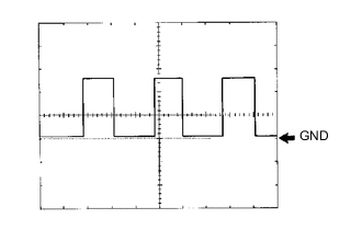
Waveform 1: Using an oscilloscope
Terminal Connections F1-6 (+S) and Body ground
F1-5 (SI) and Body ground
Tool Setting 5 V/DIV., 20 ms./DIV. Condition Driving at approximately 20 km/h (12 mph) Tech Tips
As the vehicle speed increases, the cycle of the signal waveform narrows.
-
-
-
CHECK MAIN BODY ECU (MULTIPLEX NETWORK BODY ECU) AND INSTRUMENT PANEL JUNCTION BLOCK ASSEMBLY (1 Connector Type)
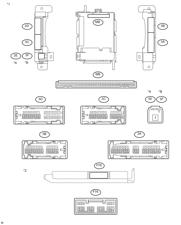
Text in Illustration *A for LHD *B for RHD *1 Instrument Panel Junction Block Assembly *2 Main Body ECU
(Multiplex Network Body ECU)
-
Remove the main body ECU (multiplex network body ECU).
-
Measure the resistance and voltage between each terminal of the wire harness side connectors and body ground.
Terminal No. (Symbol) Wiring Color Terminal Description Condition Specified Condition MB-11 (GND1) - Body ground None - Body ground Ground Always Below 1 Ω MB-29 (ACC) - Body ground None - Body ground Ignition power supply (ACC signal) Ignition switch ACC 11 to 14 V MB-30 (BECU) - Body ground None - Body ground +B (power system signal system) power supply Always 11 to 14 V MB-32 (IG) - Body ground None - Body ground Ignition power supply (IG signal) Ignition switch ON 11 to 14 V If the result is not as specified, there may be a malfunction on the wire harness side.
-
Install the main body ECU (multiplex network body ECU).
-
Measure the voltage between each terminal of the wire harness side connectors and body ground.
Terminal No. (Symbol) Wiring Color Terminal Description Condition Specified Condition 3A-28 (PKB) - Body ground R - Body ground Parking brake signal Parking brake warning light ON → OFF Below 1 V → 11 to 14 V 3D-34 (DBKL) - Body ground W - Body ground Front seat inner belt assembly signal (driver side) Driver seat belt warning light OFF → ON Below 1 V → 11 to 14 V F76-13 (CANL) - Body ground W - Body ground CAN communication line Ignition switch ON Pulse generation F76-14 (CANH) - Body ground R - Body ground CAN communication line Ignition switch ON Pulse generation If the result is not as specified, there may be a malfunction in the wire harness.
-
-
CHECK MAIN BODY ECU (MULTIPLEX NETWORK BODY ECU) AND INSTRUMENT PANEL JUNCTION BLOCK ASSEMBLY (2 Connector Type)
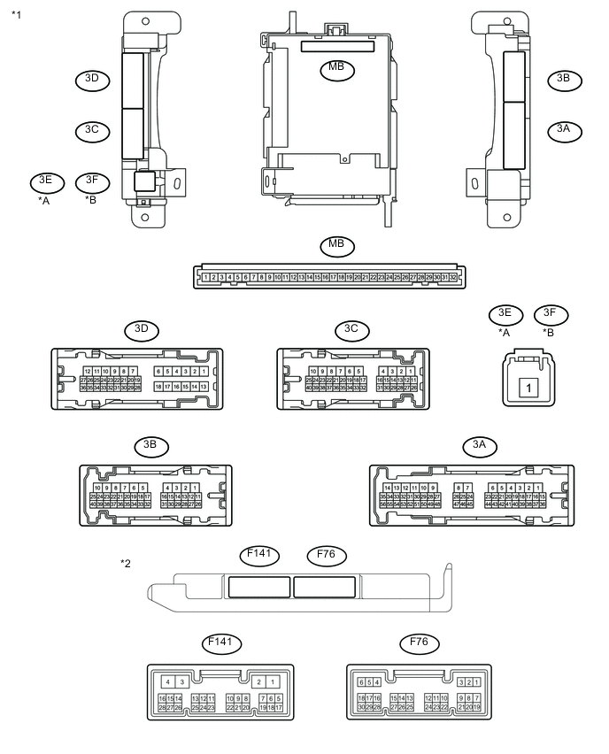
Text in Illustration *A for LHD *B for RHD *1 Instrument Panel Junction Block Assembly *2 Main Body ECU
(Multiplex Network Body ECU)
-
Remove the main body ECU (multiplex network body ECU).
-
Measure the resistance and voltage between each terminal of the wire harness side connectors and body ground.
Terminal No. (Symbol) Wiring Color Terminal Description Condition Specified Condition MB-11 (GND1) - Body ground None - Body ground Ground Always Below 1 Ω MB-29 (ACC) - Body ground None - Body ground Ignition power supply (ACC signal) Ignition switch ACC 11 to 14 V MB-30 (BECU) - Body ground None - Body ground +B (power system signal system) power supply Always 11 to 14 V MB-32 (IG) - Body ground None - Body ground Ignition power supply (IG signal) Ignition switch ON 11 to 14 V If the result is not as specified, there may be a malfunction on the wire harness side.
-
Install the main body ECU (multiplex network body ECU).
-
Measure the voltage between each terminal of the wire harness side connectors and body ground.
Terminal No. (Symbol) Wiring Color Terminal Description Condition Specified Condition 3A-28 (PKB) - Body ground R - Body ground Parking brake signal Parking brake warning light ON → OFF Below 1 V → 11 to 14 V 3D-34 (DBKL) - Body ground W - Body ground Front seat inner belt assembly signal (driver side) Driver seat belt warning light OFF → ON Below 1 V → 11 to 14 V F76-13 (CANL) - Body ground W - Body ground CAN communication line Ignition switch ON Pulse generation F76-14 (CANH) - Body ground R - Body ground CAN communication line Ignition switch ON Pulse generation If the result is not as specified, there may be a malfunction in the wire harness.
-
-
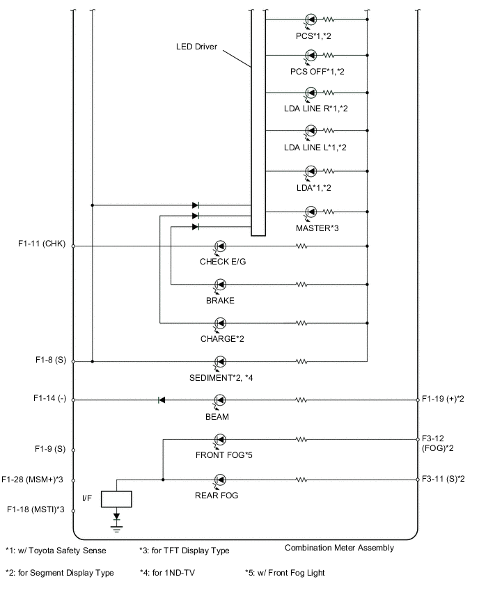
COMBINATION METER INTERNAL CIRCUIT
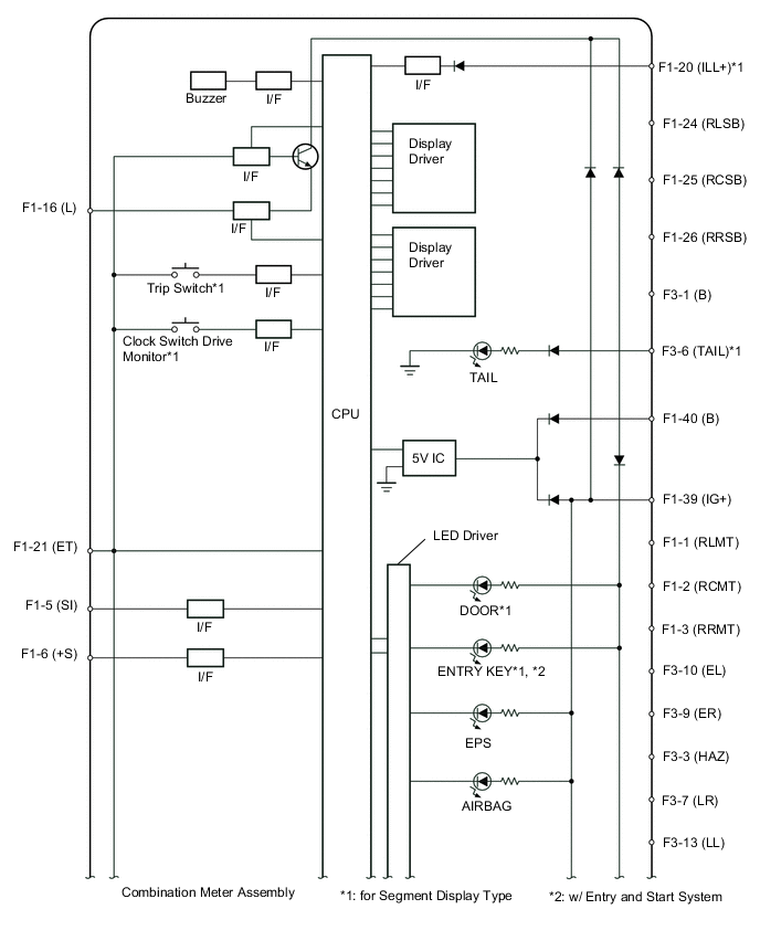
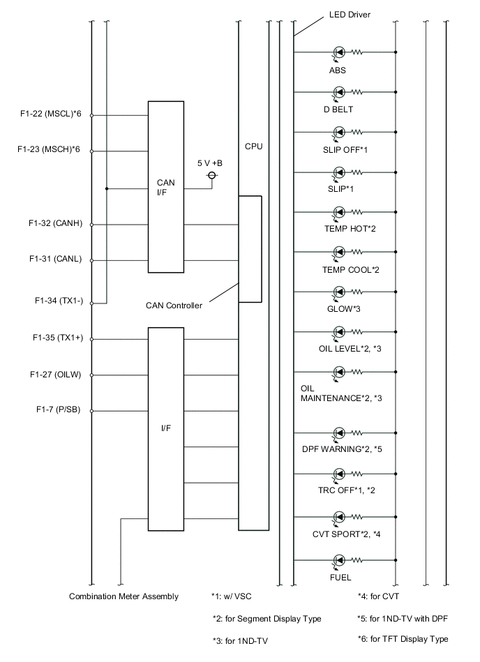
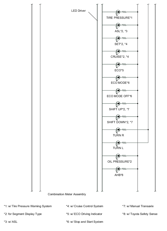
Connectors Terminal No. Wire Harness Side F1 1 Telltale light assembly (Rear Seat LH)*1 2 Telltale light assembly (Rear Seat CENTER)*1 3 Telltale light assembly (Rear Seat RH)*1 5 Brake actuator assembly (skid control ECU) 6 Other ECU 7 Occupant detection sensor and Front seat inner belt assembly (Front passenger side) 8 Fuel sedimenter warning switch*2 9 Engine oil pressure switch assembly*6 11 ECM 14 Body ground 16 Fuel sender gauge assembly 18 Steering pad switch assembly*7 19 H-LP LH HI fuse*9 20 Panel fuse*9 21 Body ground 22 CAN communication line*8 23 CAN communication line*8 24 Rear seat inner belt assembly LH*1 25 Rear seat inner belt assembly CENTER*1 26 Rear seat inner belt assembly RH*1 27 Engine oil level sensor assembly*2 28 Steering pad switch assembly*7 31 CAN communication line 32 CAN communication line 34 Thermistor assembly 35 Thermistor assembly 39 IG2 relay*3
Engine stop and start ECU*4
40 Battery F3 1 Battery 3 Hazard warning signal switch assembly 6 Panel fuse*9 7 Turn signal light RH 9 Headlight dimmer switch assembly (Turn signal switch) 10 Headlight dimmer switch assembly (Turn signal switch) 11 FOG RR relay*9 12 FOG FR relay*5, *9 13 Turn signal light LH
-
*1: w/ Rear Seat Belt Warning System
-
*2: for 1ND-TV
-
*3: w/o Stop and Start System
-
*4: w/ Stop and Start System
-
*5: w/ Fog Light
-
*6: except 1ND-TV with DPF
-
*7: for TFT Display Type
-
*8: for TFT Display Type and Radio and Display Type
-
*9: for Segment Display Type
-