LIGHTING SYSTEM Engine Switch Illumination Circuit
DESCRIPTION
The illuminated entry system controls the engine switch illumination.
WIRING DIAGRAM
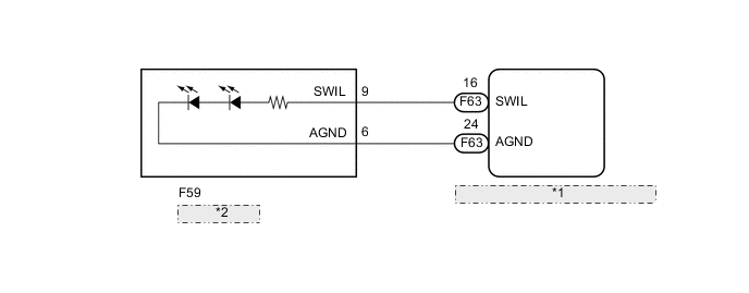
| *1 | Certification ECU (Smart Key ECU Assembly) |
| *2 | Engine Switch |
CAUTION / NOTICE / HINT
Note
Before replacing the certification ECU (smart key ECU assembly), refer to the entry and start system (for Entry Function) Click here.
PROCEDURE
-
PERFORM ACTIVE TEST USING INTELLIGENT TESTER
-
Connect the intelligent tester to the DLC3.
-
Turn the ignition switch to ON.
-
Turn the intelligent tester on.
-
Enter the following menus: Body / Main Body / Active Test.
-
According to the display on the intelligent tester, perform the Active Test.
Main Body Tester Display Test Part Control Range Diagnostic Note Illuminated Entry System Engine switch OFF or ON All door closed. OK Engine switch illumination comes on.
OK 
PROCEED TO NEXT SUSPECTED AREA SHOWN IN PROBLEM SYMPTOMS TABLE Click here
NG 
-
-
INSPECT ENGINE SWITCH
-
Inspect the engine switch.
-
for 1KR-FE Click here
-
for 2NR-FKE Click here
-
for 1ND-TV Click here
Result Result Proceed to OK A NG (for 1KR-FE) B NG (for 2NR-FKE) C NG (for 1ND-TV) D -
B
REPLACE ENGINE SWITCH Click here
C
REPLACE ENGINE SWITCH Click here
D
REPLACE ENGINE SWITCH Click here
A
-
-
CHECK HARNESS AND CONNECTOR (ENGINE SWITCH - CERTIFICATION ECU (SMART KEY ECU ASSEMBLY) AND BODY GROUND)
-
Disconnect the F59 engine switch connector.
-
Disconnect the F63 certification ECU (smart key ECU assembly) connector.
-
Measure the resistance according to the value(s) in the table below.
Standard Resistance Tester Connection Condition Specified Condition F59-9 (SWIL) - F63-16 (SWIL) Always Below 1 Ω F59-6 (AGND) - F63-24 (AGND) Always Below 1 Ω F59-9 (SWIL) - Body ground Always 10 kΩ or higher F59-6 (AGND) - Body ground Always 10 kΩ or higher
OK
REPLACE CERTIFICATION ECU (SMART KEY ECU ASSEMBLY)
NG
REPAIR OR REPLACE HARNESS OR CONNECTOR
-