LIGHTING SYSTEM Footwell Light Circuit
DESCRIPTION
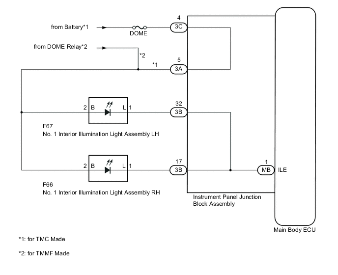
The main body ECU controls the No. 1 interior illumination light assemblies.
WIRING DIAGRAM
CAUTION / NOTICE / HINT
CAUTION:
Inspect the fuses for circuits related to this system before performing the following inspection procedure.
PROCEDURE
-
PERFORM ACTIVE TEST USING INTELLIGENT TESTER
-
Connect the intelligent tester to the DLC3.
-
Turn the ignition switch to ON.
-
Turn the intelligent tester on.
-
Enter the following menus: Body / Main Body / Active Test.
-
According to the display on the intelligent tester, perform the Active Test.
Main Body Tester Display Test Part Control Range Diagnostic Note Illuminated Entry System No. 1 interior illumination light assembly OFF or ON All doors closed OK No. 1 interior illumination light assembly comes on.
OK 
PROCEED TO NEXT SUSPECTED AREA SHOWN IN PROBLEM SYMPTOMS TABLE Click here
NG 
-
-
INSPECT NO. 1 INTERIOR ILLUMINATION LIGHT ASSEMBLY
-
Inspect the No. 1 interior illumination light assembly Click here.
Result Proceed to OK (for TMC Made) A OK (for TMMF Made) B NG C
B 
CHECK HARNESS AND CONNECTOR (NO. 1 INTERIOR ILLUMINATION LIGHTASSEMBLY - DOME RELAY) Click here
C
REPLACE NO. 1 INTERIOR ILLUMINATION LIGHT ASSEMBLY Click here
A
-
-
CHECK HARNESS AND CONNECTOR (INSTRUMENT PANEL JUNCTION BLOCK ASSEMBLY - BATTERY)
-
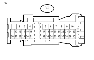
Text in Illustration *a Front view of wire harness connector
(to Instrument Panel Junction Block Assembly)
Disconnect the instrument panel junction block assembly connector.
-
Measure the voltage according to the value(s) in the table below.
Standard Voltage Tester Connection Condition Specified Condition 3C-4 - Body ground Always 11 to 14 V
NG
REPAIR OR REPLACE HARNESS OR CONNECTOR
OK
-
-
CHECK HARNESS AND CONNECTOR (NO. 1 INTERIOR ILLUMINATION LIGHT ASSEMBLY - INSTRUMENT PANEL JUNCTION BLOCK ASSEMBLY)
-
Disconnect the F67 or F66 No. 1 interior illumination light assembly connector.
-
Disconnect the 3A and 3B instrument panel junction block assembly connectors.
-
Measure the resistance according to the value(s) in the table below.
Standard Resistance LH Tester Connection Condition Specified Condition F67-2 (B) - 3A-5 Always Below 1 Ω F67-1 (L) - 3B-32 Always Below 1 Ω F67-2 (B) - Body ground Always 10 kΩ or higher F67-1 (L) - Body ground Always 10 kΩ or higher RH Tester Connection Condition Specified Condition F66-2 (B) - 3A-5 Always Below 1 Ω F66-1 (L) - 3B-17 Always Below 1 Ω F66-2 (B) - Body ground Always 10 kΩ or higher F66-1 (L) - Body ground Always 10 kΩ or higher
NG
REPAIR OR REPLACE HARNESS OR CONNECTOR
OK
-
-
INSPECT INSTRUMENT PANEL JUNCTION BLOCK ASSEMBLY
-
Remove the instrument panel junction block assembly Click here.
-
Remove the main body ECU from the instrument panel junction block assembly Click here.
-
Measure the resistance according to the value(s) in the table below.
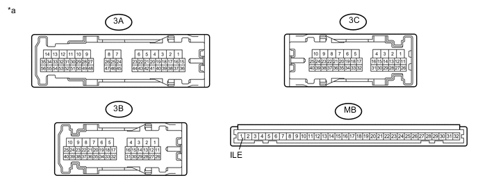
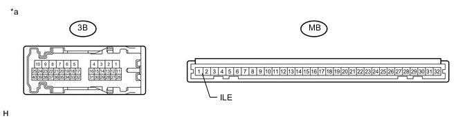
Text in Illustration *a Component without harness connected
(Instrument Panel Junction Block Assembly)
- - Standard Resistance LH Tester Connection Condition Specified Condition 3A-5 - 3C-4 Always Below 1 Ω 3B-32 - MB-1 (ILE) Always Below 1 Ω RH Tester Connection Condition Specified Condition 3A-5 - 3C-4 Always Below 1 Ω 3B-17 - MB-1 (ILE) Always Below 1 Ω
OK
REPLACE MAIN BODY ECU Click here
NG
REPLACE INSTRUMENT PANEL JUNCTION BLOCK ASSEMBLY Click here
-
-
CHECK HARNESS AND CONNECTOR (NO. 1 INTERIOR ILLUMINATION LIGHTASSEMBLY - DOME RELAY)
-
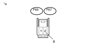
Text in Illustration *a Front view of wire harness connector
(to No. 1 Interior Illumination Light Assembly LH and RH)
Disconnect the No. 1 interior illumination light assembly connectors.
-
Measure the voltage according to the value(s) in the table below.
Standard Voltage LH Tester Connection Condition Specified Condition F67-2 (B) - Body ground Always 11 to 14 V RH Tester Connection Condition Specified Condition F66-2 (B) - Body ground Always 11 to 14 V
NG
REPAIR OR REPLACE HARNESS OR CONNECTOR
OK
-
-
CHECK HARNESS AND CONNECTOR (NO. 1 INTERIOR ILLUMINATION LIGHTASSEMBLY - INSTRUMENT PANEL JUNCTION BLOCK ASSEMBLY)
-
Disconnect the F67 and F66 No. 1 interior illumination light assembly connectors.
-
Disconnect the 3B instrument panel junction block assembly connector.
-
Measure the resistance according to the value(s) in the table below.
Standard Resistance LH Tester Connection Condition Specified Condition F67-1 (L) - 3B-32 Always Below 1 Ω F67-2 (B) - Body ground Always 10 kΩ or higher F67-1 (L) - Body ground Always 10 kΩ or higher RH Tester Connection Condition Specified Condition F66-1 (L) - 3B-17 Always Below 1 Ω F66-2 (B) - Body ground Always 10 kΩ or higher F66-1 (L) - Body ground Always 10 kΩ or higher
NG
REPAIR OR REPLACE HARNESS OR CONNECTOR
OK
-
-
INSPECT INSTRUMENT PANEL JUNCTION BLOCK ASSEMBLY
-
Remove the instrument panel junction block assembly Click here.
-
Remove the main body ECU from the instrument panel junction block assembly Click here.
-
Measure the resistance according to the value(s) in the table below.
Text in Illustration *a Component without harness connected
(Instrument Panel Junction Block Assembly)
- - Standard Resistance LH Tester Connection Condition Specified Condition 3B-32 - MB-1 (ILE) Always Below 1 Ω RH Tester Connection Condition Specified Condition 3B-17 - MB-1 (ILE) Always Below 1 Ω
OK
REPLACE MAIN BODY ECU Click here
NG
REPLACE INSTRUMENT PANEL JUNCTION BLOCK ASSEMBLY Click here
-