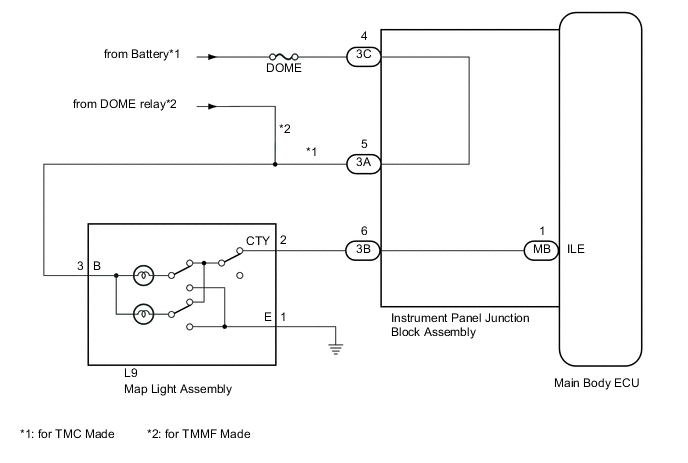
LIGHTING SYSTEM Interior Light Circuit
DESCRIPTION
The main body ECU controls the map light assembly.
WIRING DIAGRAM
CAUTION / NOTICE / HINT
Note
Inspect the fuses and bulbs for circuits related to this system before performing the following inspection procedure.
PROCEDURE
-
PERFORM ACTIVE TEST USING INTELLIGENT TESTER
-
Connect the intelligent tester to the DLC3.
-
Turn the ignition switch to ON.
-
Turn the intelligent tester on.
-
Turn the map light assembly switch to the DOOR position.
-
All doors closed (door courtesy light switches OFF).
-
Enter the following menus: Body / Main Body / Active Test.
-
According to the display on the intelligent tester, perform the Active Test.
Main Body Tester Display Test Part Control Range Diagnostic Note Illuminated Entry System Map light assembly OFF or ON Map light switch at DOOR position and all doors closed. OK The illuminated entry system operates normally when operating it through the intelligent tester.
OK 
PROCEED TO NEXT SUSPECTED AREA SHOWN IN PROBLEM SYMPTOMS TABLE Click here
NG 
-
-
INSPECT MAP LIGHT ASSEMBLY
-
Inspect the map light assembly Click here.
Result Result Proceed to OK (for TMC Made) A OK (for TMMF Made) B NG C
B 
CHECK HARNESS AND CONNECTOR (MAP LIGHT ASSEMBLY - DOME RELAY) Click here
C
REPLACE MAP LIGHT ASSEMBLY Click here
A
-
-
CHECK HARNESS AND CONNECTOR (INSTRUMENT PANEL JUNCTION BLOCK ASSEMBLY - BATTERY)
-
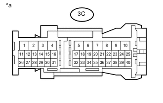
Text in Illustration *a Front view of wire harness connector
(to Instrument Panel Junction Block Assembly)
Disconnect the instrument panel junction block assembly connector.
-
Measure the voltage according to the value(s) in the table below.
Standard Voltage Tester Connection Condition Specified Condition 3C-4 - Body ground Always 11 to 14 V
NG
REPAIR OR REPLACE HARNESS OR CONNECTOR
OK
-
-
CHECK HARNESS AND CONNECTOR (MAP LIGHT ASSEMBLY - INSTRUMENT PANEL JUNCTION BLOCK ASSEMBLY AND BODY GROUND)
-
Disconnect the L9 map light assembly connector.
-
Disconnect the 3A and 3B instrument panel junction block assembly connectors.
-
Measure the resistance according to the value(s) in the table below.
Standard Resistance Tester Connection Condition Specified Condition L9-3 (B) - 3A-5 Always Below 1 Ω L9-2 (CTY) - 3B-6 Always Below 1 Ω L9-3 (B) - Body ground Always 10 kΩ or higher L9-2 (CTY) - Body ground Always 10 kΩ or higher L9-1 (E) - Body ground Always Below 1 Ω
NG
REPAIR OR REPLACE HARNESS OR CONNECTOR
OK
-
-
INSPECT INSTRUMENT PANEL JUNCTION BLOCK ASSEMBLY
-
Remove the instrument panel junction block assembly Click here.
-
Remove the main body ECU from the instrument panel junction block assembly Click here.
-
Measure the resistance according to the value(s) in the table below.
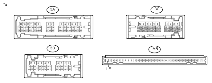
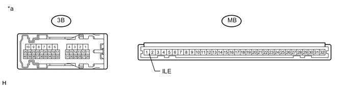
Text in Illustration *a Component without harness connected
(Instrument Panel Junction Block Assembly)
- - Standard Resistance Tester Connection Condition Specified Condition 3C-4 - 3A-5 Always Below 1 Ω 3B-6 - MB-1 (ILE) Always Below 1 Ω
OK
REPLACE MAIN BODY ECU Click here
NG
REPLACE INSTRUMENT PANEL JUNCTION BLOCK ASSEMBLY Click here
-
-
CHECK HARNESS AND CONNECTOR (MAP LIGHT ASSEMBLY - DOME RELAY)
-
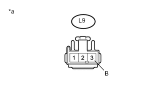
Text in Illustration *a Front view of wire harness connector
(to Map Light Assembly)
Disconnect the map light assembly connector.
-
Measure the voltage according to the value(s) in the table below.
Standard Voltage Tester Connection Condition Specified Condition L9-3 (B) - Body ground Always 11 to 14 V
NG
REPAIR OR REPLACE HARNESS OR CONNECTOR
OK
-
-
CHECK HARNESS AND CONNECTOR (MAP LIGHT ASSEMBLY - INSTRUMENT PANELJUNCTION BLOCK ASSEMBLY AND BODY GROUND)
-
Disconnect the L9 map light assembly connector.
-
Disconnect the 3B instrument panel junction block assembly connector.
-
Measure the resistance according to the value(s) in the table below.
Standard Resistance Tester Connection Condition Specified Condition L9-2 (CTY) - 3B-6 Always Below 1 Ω L9-2 (CTY) - Body ground Always 10 kΩ or higher L9-1 (E) - Body ground Always Below 1 Ω
NG
REPAIR OR REPLACE HARNESS OR CONNECTOR
OK
-
-
INSPECT INSTRUMENT PANEL JUNCTION BLOCK ASSEMBLY
-
Remove the instrument panel junction block assembly Click here.
-
Remove the main body ECU from the instrument panel junction block assembly Click here.
-
Measure the resistance according to the value(s) in the table below.
Text in Illustration *a Component without harness connected
(Instrument Panel Junction Block Assembly)
- - Standard Resistance Tester Connection Condition Specified Condition 3B-6 - MB-1 (ILE) Always Below 1 Ω
OK
REPLACE MAIN BODY ECU Click here
NG
REPLACE INSTRUMENT PANEL JUNCTION BLOCK ASSEMBLY Click here
-