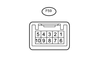
IMMOBILISER SYSTEM(except GRMN with Entry and Start System) TERMINALS OF ECU
-
CHECK ENGINE SWITCH
-
Measure the resistance and voltage according to the value(s) in the table below.
Terminal No. (Symbol) Input/Output Wiring Color Terminal Description Condition Specified Condition Related Data List Item/DTC F59-6 (AGND) - Body ground - B - Body ground Transponder key amplifier ground Always Below 1 Ω - F59-7 (TXCT) - F59-6 (AGND) Input BE - B Clock signal Engine switch off, brake pedal*1 or clutch pedal*2 not depressed, and 30 seconds or more after driver door opened and then closed Below 1 V - F59-8 (CODE) - F59-6 (AGND) Input/Output SB - B Bidirectional data communication Engine switch off, brake pedal*1 or clutch pedal*2 not depressed, and 30 seconds or more after driver door opened and then closed Below 1 V - F59-10 (VC5) - F59-6 (AGND) Input W - B Transponder key amplifier power supply Engine switch off, brake pedal*1 or clutch pedal*2 not depressed, and 30 seconds or more after driver door opened and then closed Below 1 V -
-
*1: for CVT
-
*2: for Manual Transaxle
-
-
Check for pulses according to the value(s) in the table below.
Terminal No. (Symbol) Input/Output Wiring Color Terminal Description Condition Specified Condition Related Data List Item/DTC F59-7 (TXCT) - F59-6 (AGND) Input BE - B Clock signal Engine switch off, key not inside vehicle, and within 30 seconds after engine switch pushed Pulse generation
(See waveform 1)
-
BCC Malfunction
-
Abnormal Status
-
Different Encrypt Code
-
Different Serial Number
Tech Tips
If immobiliser key code certification communication is not performed correctly, the malfunction may be indicated by one or more of the Data List items listed above
F59-8 (CODE) - F59-6 (AGND) Output SB - B Bidirectional data communication Engine switch off, and engine switch pushed while key held against engine switch* Pulse generation
(See waveform 2)
F59-10 (VC5) - F59-6 (AGND) Input W - B Transponder key amplifier power supply Engine switch off, key not inside vehicle, and within 30 seconds after engine switch pushed Pulse generation
(See waveform 3)
Tech Tips
*: Remove the transmitter battery before performing this inspection.
-
-
Inspect using an oscilloscope.
Note
The waveform shown in the illustration is an example for reference only. Noise, chattering, etc. are not shown.
-
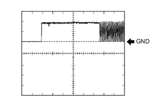
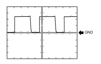
Waveform 1 (Reference)
Measurement Condition Item Content Tester Connection F59-7 (TXCT) - F59-6 (AGND) Tool Setting 2 V/DIV., 20 ms./DIV. Condition Engine switch off, key not inside vehicle, and within 30 seconds after engine switch pushed -
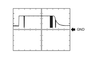
Waveform 2 (Reference)
Measurement Condition Item Content Tester Connection F59-8 (CODE) - F59-6 (AGND) Tool Setting 2 V/DIV., 20 ms./DIV. Condition Engine switch off, and engine switch pushed while key held against engine switch* Tech Tips
*: Remove the transmitter battery before performing this inspection.
-

Waveform 3 (Reference)
Measurement Condition Item Content Tester Connection F59-10 (VC5) - F59-6 (AGND) Tool Setting 2 V/DIV., 200 ms./DIV. Condition Engine switch off, key not inside vehicle, and within 30 seconds after engine switch pushed
-
-
-
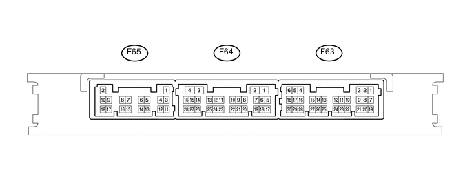
CHECK CERTIFICATION ECU (SMART KEY ECU ASSEMBLY)
-
Disconnect the F65 certification ECU (smart key ECU assembly) connector.
-
Measure the resistance and voltage according to the value(s) in the table below.
Terminal No. (Symbol) Input/Output Wiring Color Terminal Description Condition Specified Condition Related Data List Item/DTC F65-2 (+B) - F65-11 (E) Input W - BR +B power supply Always 11 to 14 V - F65-10 (CUTB) - F65-11 (E) Input Y - BR Dark current cut pin* Always 11 to 14 V - F65-11 (E) - Body ground - BR - Body ground Ground Always Below 1 Ω -
-
*: In order to prevent the battery from being depleted when the vehicle is shipped long distances, a fuse that cuts unnecessary electrical load while the vehicle is being shipped is set in the circuit. If the fuse is removed, the circuit becomes open. If the fuse between the battery and terminal CUTB is removed and the circuit is open, the certification ECU (smart key ECU assembly) changes to a certain control mode (example: the transmission of electric waves every 250 ms. that form the detection area stops).
-
-
Reconnect the F65 certification ECU (smart key ECU assembly) connector.
-
Measure the resistance and voltage according to the value(s) in the table below.
Terminal No. (Symbol) Input/Output Wiring Color Terminal Description Condition Specified Condition Related Data List Item/DTC F63-5 (IG) - F65-11 (E) Input P - BR Engine switch power supply Engine switch off → on (IG) Below 1 V → 11 to 14 V Ignition Switch F63-9 (TXCT) - F63-24 (AGND) Output BE - B Clock signal Engine switch off, brake pedal*1 or clutch pedal*2 not depressed, and 30 seconds or more after driver door opened and then closed Below 1 V
-
BCC Malfunction
-
Abnormal Status
-
Different Encrypt Code
-
Different Serial Number
F63-7 (CODE) - F63-24 (AGND) Input SB - B Signal input from transponder key amplifier Engine switch off, brake pedal*1 or clutch pedal*2 not depressed, and 30 seconds or more after driver door opened and then closed Below 1 V F63-1 (VC5) - F63-24 (AGND) Output W - B Transponder key amplifier power supply Engine switch off, brake pedal*1 or clutch pedal*2 not depressed, and 30 seconds or more after driver door opened and then closed Below 1 V F63-24 (AGND) - Body ground - B - Body ground Transponder key amplifier ground Always Below 1 Ω
-
*1: for CVT
-
*2: for Manual Transaxle
-
-
Check for pulses according to the value(s) in the table below.
Terminal No. (Symbol) Input/Output Wiring Color Terminal Description Condition Specified Condition Related Data List Item/DTC F63-9 (TXCT) - F63-24 (AGND) Output BE - B Clock signal Engine switch off, key not inside vehicle, and within 30 seconds after engine switch pushed Pulse generation
(See waveform 1)
-
BCC Malfunction
-
Abnormal Status
-
Different Encrypt Code
-
Different Serial Number
F63-7 (CODE) - F63-24 (AGND) Input SB - B Signal input from transponder key amplifier Engine switch off, and engine switch pushed while key held against engine switch* Pulse generation
(See waveform 2)
F63-1 (VC5) - F63-24 (AGND) Output W - B Transponder key amplifier power supply Engine switch off, key not inside vehicle, and within 30 seconds after engine switch pushed Pulse generation
(See waveform 3)
Tech Tips
*: Remove the transmitter battery before performing this inspection.
-
-
Inspect using an oscilloscope.
Note
The waveform shown in the illustration is an example for reference only. Noise, chattering, etc. are not shown.
-

Waveform 1 (Reference)
Measurement Condition Item Content Tester Connection F63-9 (TXCT) - F63-24 (AGND) Tool Setting 2 V/DIV., 20 ms./DIV. Condition Engine switch off, key not inside vehicle, and within 30 seconds after engine switch pushed -

Waveform 2 (Reference)
Measurement Condition Item Content Tester Connection F63-7 (CODE) - F63-24 (AGND) Tool Setting 2 V/DIV., 20 ms./DIV. Condition Engine switch off, and engine switch pushed while key held against engine switch* Tech Tips
*: Remove the transmitter battery before performing this inspection.
-
Waveform 3 (Reference)
Measurement Condition Item Content Tester Connection F63-1 (VC5) - F63-24 (AGND) Tool Setting 2 V/DIV., 200 ms./DIV. Condition Engine switch off, key not inside vehicle, and within 30 seconds after engine switch pushed
-
-
-
CHECK ID CODE BOX (IMMOBILISER CODE ECU)
-
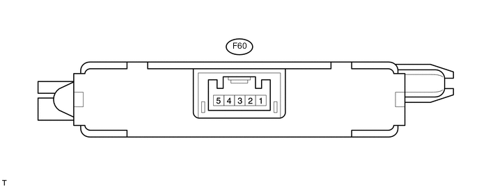
Disconnect the F60 ID code box (immobiliser code ECU) connector.
-
Measure the resistance and voltage according to the value(s) in the table below.
Terminal No. (Symbol) Input/Output Wiring Color Terminal Description Condition Specified Condition Related Data List Item/DTC F60-1 (+B) - F60-5 (GND) Input BE - BR +B power supply Always 11 to 14 V B2789 F60-5 (GND) - Body ground - BR - Body ground Ground Always Below 1 Ω B2789 If the result is not as specified, there may be a malfunction on the wire harness side.
-
Reconnect the F60 ID code box (immobiliser code ECU) connector.
-
Measure the voltage and check for pulses according to the value(s) in the table below.
Terminal No. (Symbol) Input/Output Wiring Color Terminal Description Condition Specified Condition Related Data List Item/DTC F60-3 (EFII) - F60-5 (GND) Input LG - BR EFI communication input
(Signal input from ECM to ID code box (immobiliser code ECU))
Engine switch off 11 to 14 V
-
B2799
-
B279A
-
Engine Start Request
-
EFI Code Receive
EFI communication input
(Signal input from ECM to ID code box (immobiliser code ECU))
Within 3 seconds of engine start or within 3 seconds of engine switch turned on (IG) after battery cable disconnected and reconnected Pulse generation
(See waveform 1)
F60-4 (EFIO) - F60-5 (GND) Output R - BR EFI communication output
(Signal output from ID code box (immobiliser code ECU) to ECM)
Engine switch off 11 to 14 V EFI communication output
(Signal output from ID code box (immobiliser code ECU) to ECM)
Engine switch off → on (IG) Pulse generation
(See waveform 2)
-
-
Inspect using an oscilloscope.
Note
The waveform shown in the illustration is an example for reference only. Noise, chattering, etc. are not shown.
-
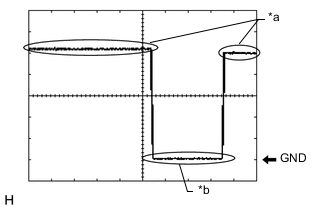
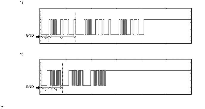
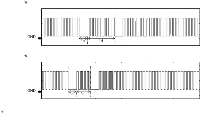
Waveform 1 (Reference)

Text in Illustration *a Waveform A *b Waveform B *c Approximately 160 ms *d Approximately 510 ms *e Approximately 270 ms - - Measurement Condition Item Content Tester Connection F60-3 (EFII) - F60-5 (GND) Tool Setting 2 V/DIV., 500 ms./DIV. Condition Within 3 seconds of engine start or within 3 seconds of engine switch turned on (IG) after battery cable disconnected and reconnected -
Waveform 2 (Reference)

Text in Illustration *a Waveform A *b Waveform B *c Approximately 160 ms *d Approximately 510 ms *e Approximately 270 ms - - Measurement Condition Item Content Tester Connection F60-4 (EFIO) - F60-5 (GND) Tool Setting 2 V/DIV., 500 ms./DIV. Condition Within 3 seconds of engine start or within 3 seconds of engine switch turned on (IG) after battery cable disconnected and reconnected
-
-
-
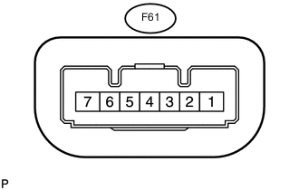
CHECK STEERING LOCK ACTUATOR ASSEMBLY (STEERING LOCK ECU)
-
Measure the resistance and voltage and check for pulses according to the value(s) in the table below.
Terminal No. (Symbol) Input/Output Wiring Color Terminal Description Condition Specified Condition Related Data List Item/DTC F61-1 (GND) - Body ground - W-B - Body ground Ground Always Below 1 Ω - F61-3 (IGE) - Body ground Input L - Body ground Steering lock motor activation command signal (motor activation command signal sent from certification ECU (smart key ECU assembly)) Any door opened when conditions below met, and then steering lock motor activated:
-
Shift lever is in P
-
Steering lock unlocked in advance by carrying key and turning engine switch on (IG)
-
After above condition met, engine switch turned off
Pulse generation
(See waveform 1)
-
Power Supply Short
-
Unlock Request Receive
-
Lock Request Receive
F61-4 (SLP1) - Body ground Output P - Body ground Steering lock bar position signal (output signal from steering unlock sensor) Steering locked → unlocked*2 11 to 14 V → Below 1.2 V
-
Push Start Error
-
Sensor Value
F61-6 (IG2) - Body ground Input SB - Body ground Power source mode signal (IG2 power supply input for entire steering lock actuator assembly) Engine switch off → on (IG) Below 1 V → 11 to 14 V
-
B2788
-
Ignition Switch
F61-7 (B) - Body ground Input GR - Body ground Power source Always 11 to 14 V B2788
-
*1: for CVT
Tech Tips
-
*2: The steering locks when any door is opened with the shift lever in P (for CVT) and the engine switch off. The steering unlocks when the engine switch is turned on (ACC).
-
-
Inspect using an oscilloscope.
Note
The waveform shown in the illustration is an example for reference only. Noise, chattering, etc. are not shown.
-
Text in Illustration *a Steering lock motor not operating *b Steering lock motor operating Waveform 1 (Reference)
Measurement Condition Item Content Tester Connection F61-3 (IGE) - F61-1 (GND) Tool Setting 2 V/DIV., 200 ms./DIV. Condition Steering lock motor operates when both conditions met, and then door opened:
-
Shift lever is in P*1
-
Steering lock unlocked in advance by carrying key and turning engine switch on (IG)
-
After above condition met, engine switch turned off
-
*1: for CVT
-
-
-
-
CHECK ECM (for 1KR-FE)
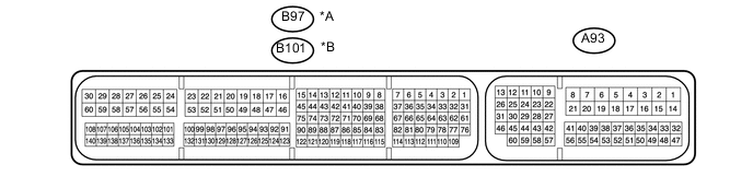
Text in Illustration *A for LHD *B for RHD
-
Measure the resistance and voltage and check for pulses according to the value(s) in the table below.
Terminal No. (Symbol) Input/Output Wiring Color Terminal Description Condition Specified Condition Related Data List Item/DTC A93-4 (E1) - Body ground - W-B - Body ground Ground Always Below 1 Ω - A93-15 (BATT) - A93-4 (E1) Input V - W-B +B power supply Always 11 to 14 V - A93-1 (+B1) - A93-4 (E1) Input B - W-B +B power supply Engine switch on (IG) 11 to 14 V - A93-2 (+B) - A93-4 (E1) Input B - W-B +B power supply Engine switch on (IG) 11 to 14 V - A93-43 (IMO) - A93-4 (E1) Input W - W-B ID code box (immobiliser code ECU) communication input Engine switch off 11 to 14 V - ID code box (immobiliser code ECU) communication input Within 3 seconds of engine start or within 3 seconds of engine switch turned on (IG) after battery cable disconnected and reconnected Pulse generation
(See waveform 1)
- A93-42 (IMI) - A93-4 (E1) Output G - W-B ID code box (immobiliser code ECU) communication output Engine switch off 11 to 14 V - ID code box (immobiliser code ECU) communication output Within 3 seconds of engine start or within 3 seconds of engine switch turned on (IG) after battery cable disconnected and reconnected Pulse generation
(See waveform 2)
- If the result is not as specified, the ECM may have a malfunction.
-
Inspect using an oscilloscope.
Note
The waveform shown in the illustration is an example for reference only. Noise, chattering, etc. are not shown.
-
Waveform 1 (Reference)

Text in Illustration *a Waveform A *b Waveform B *c Approximately 160 ms *d Approximately 510 ms *e Approximately 270 ms - - Measurement Condition Item Content Tester Connection A93-43 (IMO) - A93-4 (E1) Tool Setting 2 V/DIV., 500 ms./DIV. Condition Within 3 seconds of engine start or within 3 seconds of engine switch turned on (IG) after battery cable disconnected and reconnected -
Waveform 2 (Reference)

Text in Illustration *a Waveform A *b Waveform B *c Approximately 160 ms *d Approximately 510 ms *e Approximately 270 ms - - Measurement Condition Item Content Tester Connection A93-42 (IMI) - A93-4 (E1) Tool Setting 2 V/DIV., 500 ms./DIV. Condition Within 3 seconds of engine start or within 3 seconds of engine switch turned on (IG) after battery cable disconnected and reconnected
-
-
-
CHECK ECM (for 2NR-FKE)
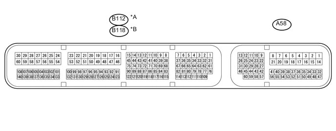
Text in Illustration *A for LHD *B for RHD
-
Measure the resistance and voltage and check for pulses according to the value(s) in the table below.
for LHD Terminal No. (Symbol) Input/Output Wiring Color Terminal Description Condition Specified Condition Related Data List Item/DTC B112-59 (E1) - Body ground - W-B - Body ground Ground Always Below 1 Ω - A58-1 (BATT) - B112-59 (E1) Input Y - W-B +B power supply Always 11 to 14 V - A58-3 (+B2) - B112-59 (E1) Input B - W-B +B power supply Engine switch on (IG) 11 to 14 V - A58-2 (+B) - B112-59 (E1) Input B - W-B +B power supply Engine switch on (IG) 11 to 14 V - A58-45 (IMO) - B112-59 (E1) Input W - W-B ID code box (immobiliser code ECU) communication input Engine switch off 11 to 14 V - ID code box (immobiliser code ECU) communication input Within 3 seconds of engine start or within 3 seconds of engine switch turned on (IG) after battery cable disconnected and reconnected Pulse generation
(See waveform 1)
- A58-28 (IMI) - B112-59 (E1) Output G - W-B ID code box (immobiliser code ECU) communication output Engine switch off 11 to 14 V - ID code box (immobiliser code ECU) communication output Within 3 seconds of engine start or within 3 seconds of engine switch turned on (IG) after battery cable disconnected and reconnected Pulse generation
(See waveform 2)
- for RHD Terminal No. (Symbol) Input/Output Wiring Color Terminal Description Condition Specified Condition Related Data List Item/DTC B118-59 (E1) - Body ground - W-B - Body ground Ground Always Below 1 Ω - A58-1 (BATT) - B118-59 (E1) Input Y - W-B +B power supply Always 11 to 14 V - A58-3 (+B2) - B118-59 (E1) Input B - W-B +B power supply Engine switch on (IG) 11 to 14 V - A58-2 (+B) - B118-59 (E1) Input B - W-B +B power supply Engine switch on (IG) 11 to 14 V - A58-45 (IMO) - B118-59 (E1) Input W - W-B ID code box (immobiliser code ECU) communication input Engine switch off 11 to 14 V - ID code box (immobiliser code ECU) communication input Within 3 seconds of engine start or within 3 seconds of engine switch turned on (IG) after battery cable disconnected and reconnected Pulse generation
(See waveform 1)
- A58-28 (IMI) - B118-59 (E1) Output G - W-B ID code box (immobiliser code ECU) communication output Engine switch off 11 to 14 V - ID code box (immobiliser code ECU) communication output Within 3 seconds of engine start or within 3 seconds of engine switch turned on (IG) after battery cable disconnected and reconnected Pulse generation
(See waveform 2)
- If the result is not as specified, the ECM may have a malfunction.
-
Inspect using an oscilloscope.
Note
The waveform shown in the illustration is an example for reference only. Noise, chattering, etc. are not shown.
-
Waveform 1 (Reference)
Text in Illustration *a Waveform A *b Waveform B *c Approximately 160 ms *d Approximately 510 ms *e Approximately 270 ms - - Measurement Condition Item Content Tester Connection A58-45 (IMO) - B112-59 (E1)*1
A58-45 (IMO) - B118-59 (E1)*2
Tool Setting 2 V/DIV., 500 ms./DIV. Condition Within 3 seconds of engine start or within 3 seconds of engine switch turned on (IG) after battery cable disconnected and reconnected
-
*1: for LHD
-
*2: for RHD
-
-
Waveform 2 (Reference)

Text in Illustration *a Waveform A *b Waveform B *c Approximately 160 ms *d Approximately 510 ms *e Approximately 270 ms - - Measurement Condition Item Content Tester Connection A58-28 (IMI) - B112-59 (E1)*1
A58-28 (IMI) - B118-59 (E1)*2
Tool Setting 2 V/DIV., 500 ms./DIV. Condition Within 3 seconds of engine start or within 3 seconds of engine switch turned on (IG) after battery cable disconnected and reconnected
-
*1: for LHD
-
*2: for RHD
-
-
-
-
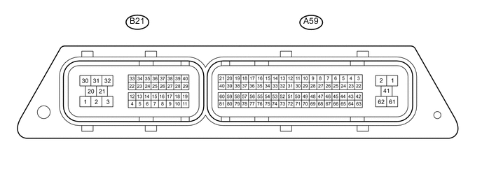
CHECK ECM (for 1ND-TV without DPF)
-
Measure the resistance and voltage and check for pulses according to the value(s) in the table below.
Terminal No. (Symbol) Input/Output Wiring Color Terminal Description Condition Specified Condition Related Data List Item/DTC A59-2 (E1) - Body ground - W-B - Body ground Ground Always Below 1 Ω - A59-23 (BATT) - A59-2 (E1) Input V - W-B +B power supply Always 11 to 14 V - A59-61 (+B2) - A59-2 (E1) Input B - W-B +B power supply Engine switch on (IG) 11 to 14 V - A59-1 (+B) - A59-2 (E1) Input B - W-B +B power supply Engine switch on (IG) 11 to 14 V - A59-78 (IMO) - A59-2 (E1) Input W - W-B ID code box (immobiliser code ECU) communication input Engine switch off 11 to 14 V - ID code box (immobiliser code ECU) communication input Within 3 seconds after starter operates and initial combustion occurs, or within 3 seconds after engine switch first turned to ON after battery disconnected and connected. Pulse generation
(See waveform 1)
- A59-77 (IMI) - A59-2 (E1) Output G - W-B ID code box (immobiliser code ECU) communication output Engine switch off 11 to 14 V - ID code box (immobiliser code ECU) communication output Within 3 seconds after starter operates and initial combustion occurs, or within 3 seconds after engine switch first turned to ON after battery disconnected and connected. Pulse generation
(See waveform 2)
- If the result is not as specified, the ECM may have a malfunction.
-
Inspect using an oscilloscope.
Note
The waveform shown in the illustration is an example for reference only. Noise, chattering, etc. are not shown.
-
Waveform 1 (Reference)

Text in Illustration *a Waveform A *b Waveform B *c Approximately 160 ms *d Approximately 510 ms *e Approximately 270 ms - - Measurement Condition Item Content Tester Connection A59-78 (IMO) - A59-2 (E1) Tool Setting 2 V/DIV., 500 ms./DIV. Condition Within 3 seconds of engine start or within 3 seconds of engine switch turned on (IG) after battery cable disconnected and reconnected -
Waveform 2 (Reference)
Text in Illustration *a Waveform A *b Waveform B *c Approximately 160 ms *d Approximately 510 ms *e Approximately 270 ms - - Measurement Condition Item Content Tester Connection A59-77 (IMI) - A59-2 (E1) Tool Setting 2 V/DIV., 500 ms./DIV. Condition Within 3 seconds of engine start or within 3 seconds of engine switch turned on (IG) after battery cable disconnected and reconnected
-
-
-
CHECK ECM (for 1ND-TV with DPF)
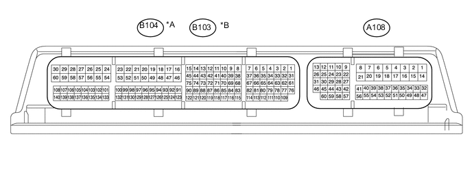
Text in Illustration *A for LHD *B for RHD
-
Measure the resistance and voltage and check for pulses according to the value(s) in the table below.
Terminal No. (Symbol) Input/Output Wiring Color Terminal Description Condition Specified Condition Related Data List Item/DTC A108-4 (E1) - Body ground - W-B - Body ground Ground Always Below 1 Ω - A108-15 (BATT) - A108-4 (E1) Input V - W-B +B power supply Always 11 to 14 V - A108-14 (+B2) - A108-4 (E1) Input B - W-B +B power supply Engine switch on (IG) 11 to 14 V - A108-2 (+B) - A108-4 (E1) Input B - W-B +B power supply Engine switch on (IG) 11 to 14 V - A108-1 (+B3) - A108-4 (E1) Input B - W-B +B power supply Engine switch on (IG) 11 to 14 V - A108-29 (IMO) - A108-4 (E1) Input W - W-B ID code box (immobiliser code ECU) communication input Engine switch off 11 to 14 V - ID code box (immobiliser code ECU) communication input Within 3 seconds after starter operates and initial combustion occurs, or within 3 seconds after engine switch first turned to ON after battery disconnected and connected. Pulse generation
(See waveform 1)
- A108-34 (IMI) - A108-4 (E1) Output G - W-B ID code box (immobiliser code ECU) communication output Engine switch off 11 to 14 V - ID code box (immobiliser code ECU) communication output Within 3 seconds after starter operates and initial combustion occurs, or within 3 seconds after engine switch first turned to ON after battery disconnected and connected. Pulse generation
(See waveform 2)
- If the result is not as specified, the ECM may have a malfunction.
-
Inspect using an oscilloscope.
Note
The waveform shown in the illustration is an example for reference only. Noise, chattering, etc. are not shown.
-
Waveform 1 (Reference)
Text in Illustration *a Waveform A *b Waveform B *c Approximately 160 ms *d Approximately 510 ms *e Approximately 270 ms - - Measurement Condition Item Content Tester Connection A108-29 (IMO) - A108-4 (E1) Tool Setting 2 V/DIV., 500 ms./DIV. Condition Within 3 seconds of engine start or within 3 seconds of engine switch turned on (IG) after battery cable disconnected and reconnected -
Waveform 2 (Reference)
Text in Illustration *a Waveform A *b Waveform B *c Approximately 160 ms *d Approximately 510 ms *e Approximately 270 ms - - Measurement Condition Item Content Tester Connection A108-34 (IMI) - A108-4 (E1) Tool Setting 2 V/DIV., 500 ms./DIV. Condition Within 3 seconds of engine start or within 3 seconds of engine switch turned on (IG) after battery cable disconnected and reconnected
-
-