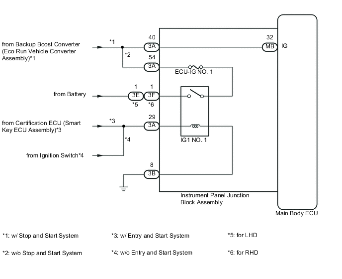
LIGHTING SYSTEM IG Signal Circuit
DESCRIPTION
This circuit detects the ignition switch ON or off condition, and sends it to the main body ECU.
WIRING DIAGRAM
CAUTION / NOTICE / HINT
Note
Inspect the fuses for circuits related to this system before performing the following inspection procedure.
PROCEDURE
-
READ VALUE USING INTELLIGENT TESTER
-
Connect the intelligent tester to the DLC3.
-
Turn the ignition switch to ON.
-
Turn the intelligent tester on.
-
Enter the following menus: Body / Main Body / Data List.
-
According to the display on the intelligent tester, read the Data List.
Main Body Tester Display Measurement Item/Range Normal Condition Diagnostic Note IG SW Ignition switch ON signal /
OFF or ON
OFF: Ignition switch ACC or off
ON: Ignition switch ON
- OK Normal conditions listed above are displayed. Result Result Proceed to OK A NG (w/ Stop and Start System) B NG (w/o Stop and Start System) C
A 
PROCEED TO NEXT SUSPECTED AREA SHOWN IN PROBLEM SYMPTOMS TABLE Click here
C 
CHECK HARNESS AND CONNECTOR (INSTRUMENT PANEL JUNCTION BLOCK ASSEMBLY - BATTERY AND BODY GROUND) Click here
B 
-
-
CHECK HARNESS AND CONNECTOR (INSTRUMENT PANEL JUNCTION BLOCK ASSEMBLY - BACKUP BOOST CONVERTER)
-
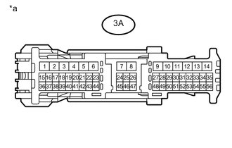
Text in Illustration *a Front view of wire harness connector
(to Instrument Panel Junction Block Assembly)
Disconnect the 3A instrument panel junction block assembly connector.
-
Measure the voltage according to the value(s) in the table below.
Standard Voltage Tester Connection Switch Condition Specified Condition 3A-40 - Body ground Ignition switch ON 11 to 14 V Result Result Proceed to NG A OK B
A
GO TO STOP AND START SYSTEM Click here
B
REPLACE MAIN BODY ECU Click here
-
-
CHECK HARNESS AND CONNECTOR (INSTRUMENT PANEL JUNCTION BLOCK ASSEMBLY - BATTERY AND BODY GROUND)
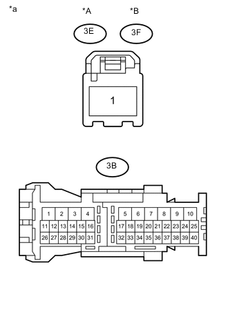
Text in Illustration *A for LHD *B for RHD *a Front view of wire harness connector
(to Instrument Panel Junction Block Assembly)
-
for LHD
-
Disconnect the 3E and 3B instrument panel junction block assembly connectors.
-
-
for RHD
-
Disconnect the 3F and 3B instrument panel junction block assembly connectors.
-
-
Measure the voltage according to the value(s) in the table below.
Standard Voltage for LHD Tester Connection Switch Condition Specified Condition 3E-1 - Body ground Always 11 to 14 V for RHD Tester Connection Switch Condition Specified Condition 3F-1 - Body ground Always 11 to 14 V -
Measure the resistance according to the value(s) in the table below.
Standard Resistance Tester Connection Condition Specified Condition 3B-8 - Body ground Always Below 1 Ω
NG
REPAIR OR REPLACE HARNESS OR CONNECTOR
OK
-
-
CHECK HARNESS AND CONNECTOR (INSTRUMENT PANEL JUNCTION BLOCK ASSEMBLY - CERTIFICATION ECU OR IGNITION SWITCH)
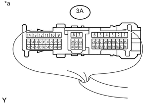
Text in Illustration *a Component with harness connected
(Instrument Panel Junction Block Assembly)
-
Reconnect the instrument panel junction block assembly connectors.
-
Measure the voltage according to the value(s) in the table below.
Standard Voltage Tester Connection Switch Condition Specified Condition 3A-29 - Body ground Ignition switch ON 11 to 14 V
NG
REPAIR OR REPLACE HARNESS OR CONNECTOR
OK
-
-
CHECK HARNESS AND CONNECTOR (INSTRUMENT PANEL JUNCTION BLOCK ASSEMBLY)
-
Disconnect the 3A instrument panel junction block assembly connector.
-
Measure the resistance according to the value(s) in the table below.
Standard Resistance Tester Connection Condition Specified Condition 3A-40 - 3A-54 Always Below 1 Ω 3A-40 - Body ground Always 10 kΩ or higher
NG
REPAIR OR REPLACE HARNESS OR CONNECTOR
OK
-
-
REPLACE MAIN BODY ECU
-
Temporarily replace the main body ECU with a new functioning one Click here.
NEXT
-
-
READ VALUE USING INTELLIGENT TESTER
-
Connect the intelligent tester to the DLC3.
-
Turn the ignition switch to ON.
-
Turn the intelligent tester on.
-
Enter the following menus: Body / Main Body / Data List.
-
According to the display on the intelligent tester, read the Data List.
Main Body Tester Display Measurement Item/Range Normal Condition Diagnostic Note IG SW Ignition switch ON signal /
OFF or ON
OFF: Ignition switch ACC or off
ON: Ignition switch ON
- OK Normal conditions listed above are displayed.
OK
END (MAIN BODY ECU DEFECTIVE)
NG
REPLACE INSTRUMENT PANEL JUNCTION BLOCK ASSEMBLY
-