LIGHTING SYSTEM TERMINALS OF ECU
-
CHECK INSTRUMENT PANEL JUNCTION BLOCK ASSEMBLY AND MAIN BODY ECU
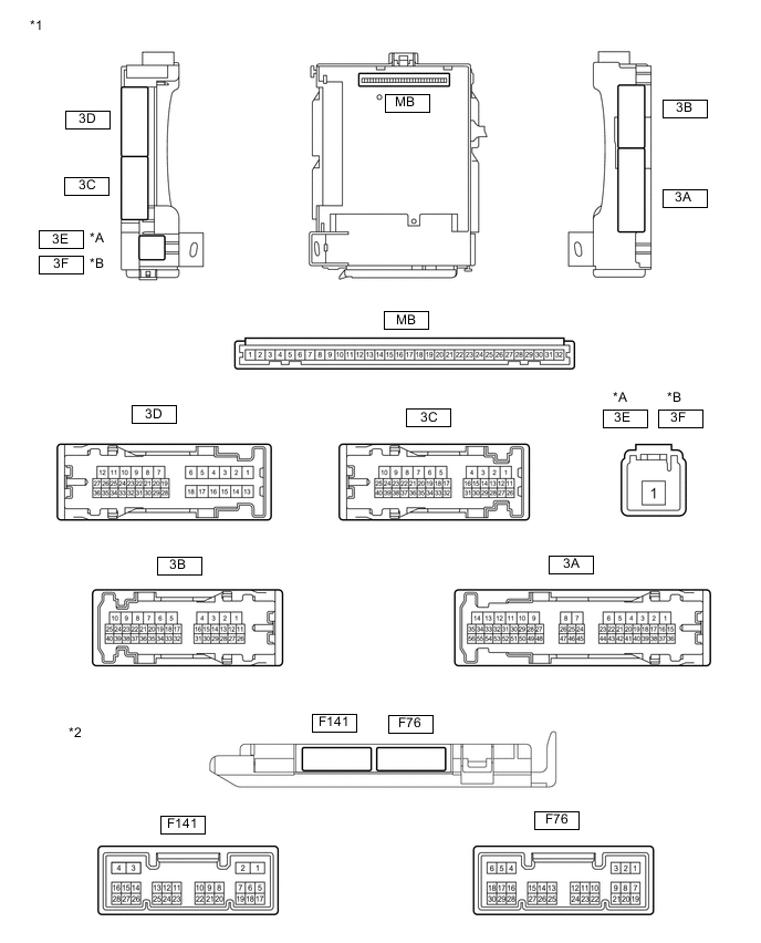
*A for LHD *B for RHD *1 Instrument Panel Junction Block Assembly *2 Main Body ECU
-
Remove the main body ECU.
-
Measure the voltage and resistance according to the value(s) in the table below.
Terminal No. (Symbol) Wiring Color Terminal Description Condition Specified Condition MB-3 (BCYL) - Body ground - Battery power supply Always 11 to 14 V MB-11 (GND1) - Body ground - Ground Always Below 1 Ω MB-29 (ACC) - Body ground - Ignition power supply (ACC signal) Ignition switch ACC 11 to 14 V MB-30 (BECU) - Body ground - Battery power supply Always 11 to 14 V MB-32 (IG)- Body ground - Ignition power supply (IG signal) Ignition switch ON 11 to 14 V If the result is not as specified, there may be a malfunction in the wire harness.
-
Reinstall the main body ECU.
-
Measure the voltage according to the value(s) in the table below.
Terminal No. (Symbol) Wiring Color Terminal Description Condition Specified Condition F141-5 (LCTY) - Body ground*1 V - Body ground Rear door LH courtesy light switch input Rear door LH open Below 1 V Rear door LH closed Pulse generation F76-6 (RCTY) - Body ground*1 G - Body ground Rear door RH courtesy light switch input Rear door RH open Below 1 V Rear door RH closed Pulse generation F76-7 (LSFL) - Body ground L - Body ground*3
R - Body ground*4
Front door LH unlock detection switch signal Front door LH locked Pulse generation Front door LH unlocked Below 1 V F76-13 (CANL) - Body ground W - Body ground CAN communication Ignition switch ON Pulse generation F76-14 (CANH) - Body ground R - Body ground CAN communication Ignition switch ON Pulse generation F76-18 (LSFR) - Body ground LG - Body ground Front door RH unlock detection switch signal Front door RH locked Pulse generation Front door RH unlocked Below 1 V F76-19 (FRCY) - Body ground Y - Body ground Front door courtesy light switch RH signal Front door RH opened Below 1 V Front door RH closed Pulse generation 3A-5 (BCYL) - Body ground SB - Body ground Battery power supply Always 11 to 14 V 3B-6 (ILE) - Body ground B - Body ground Illumination signal Map light switch in DOOR position and map light assembly turns on Below 1 V Map light switch in DOOR position and map light assembly turns off 11 to 14 V Footwell light off*2 Below 1 V Footwell light on*2 11 to 14 V 3D-6 (BCTL) - Body ground L - Body ground No. 2 room light power supply Always 11 to 14 V 3D-24 (LSR) - Body ground*1 Y - Body ground Rear door unlock detection switch signal Rear door LH and RH locked Pulse generation Rear door LH or RH unlocked Below 1 V 3D-25 (LSR) - Body ground*1 V - Body ground Rear door unlock detection switch signal Rear door LH and RH locked Pulse generation Rear door LH or RH unlocked Below 1 V 3B-33 (DOMR) - Body ground P - Body ground DOME relay output signal (to DOME relay) DOME relay off 11 to 14 V DOME relay on Below 1 V 3D-35 (BCTY) - Body ground B - Body ground Back door courtesy switch signal Back door opened Below 1 V Back door closed 11 to 14 V 3D-36 (FLCY) - Body ground L - Body ground Front door courtesy light switch LH signal Front door LH opened Below 1 V Front door LH closed Pulse generation
-
*1: for 5 Door
-
*2: w/ Foot Light
-
*3: w/o Automatic Retractable Mirror
-
*4: w/ Automatic Retractable Mirror
Tech Tips
If the result is not as specified, the main body ECU or instrument panel junction block assembly may have a malfunction.
-
-
-
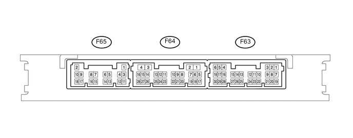
CHECK CERTIFICATION ECU (SMART KEY ECU ASSEMBLY)
-
Measure the voltage according to the value(s) in the table below.
Terminal No. (Symbol) Wiring Color Terminal Description Condition Specified Condition F63-16 (SWIL) - Body ground R - Body ground Engine switch illumination drive signal Engine switch illumination on 9 to 14 V Engine switch illumination off Below 2 V Tech Tips
If the result is not as specified, the certification ECU (smart key ECU assembly) may have a malfunction.
-