ENGINE IMMOBILISER SYSTEM(w/o Entry and Start System) Engine does not Start but Initial Combustion Occurs
DESCRIPTION
If the key ID codes of the key and transponder key ECU assembly match, the immobiliser system is unset and the engine start permission signal is sent to the ECM. When the ID codes of the transponder key ECU assembly and ECM match, the engine starts.
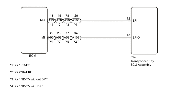
WIRING DIAGRAM
CAUTION / NOTICE / HINT
Note
When replacing the key and transponder key ECU assembly, refer to the Service Bulletin.
PROCEDURE
-
CHECK FOR DTC
-
Check for DTCs Click here.
Tech Tips
Before checking for DTCs, perform the "DTC Output Confirmation Operation" procedure.
Result Result Proceed to No DTC output A DTC output B
B 
GO TO DIAGNOSTIC TROUBLE CODE CHART Click here
A 
-
-
CONFIRM ENGINE MODELS
-
Check the vehicle specifications.
Result Result Proceed to for 2NR-FKE or 1KR-FE A for 1ND-TV B
B 
CHECK WHETHER ENGINE STARTS Click here
A
-
-
READ VALUE USING GTS (IMMOBILISER FUEL CUT)
-
Turn the ignition switch off.
-
Connect the GTS to the DLC3.
-
Turn the ignition switch to ON.
-
Turn the GTS on.
-
Enter the following menus: Powertrain / Engine and ECT / Data List.
Engine and ECT Tester Display Measurement Item/Range Normal Condition Stored as Freeze Frame Data Immobiliser Fuel Cut Status of immobiliser fuel cut/
ON or OFF
- Yes OK The item in the Data List indicates "OFF" Result Result Proceed to NG A OK (for 1KR-FE) B OK (for 2NR-FKE) C
B
GO TO SFI SYSTEM Click here
C
GO TO SFI SYSTEM Click here
A
-
-
CHECK WHETHER ENGINE STARTS
-
It leaves for 5 seconds by the ignition switch ON status, and the engine starting operation is done.
Result Result Proceed to Engine cannot be started A Engine can be started B
B
USE SIMULATION METHOD TO CHECK Click here
A
-
-
CHECK ECM (TERMINAL IMI)
-
for 1KR-FE
-
Using an oscilloscope, check the waveform.
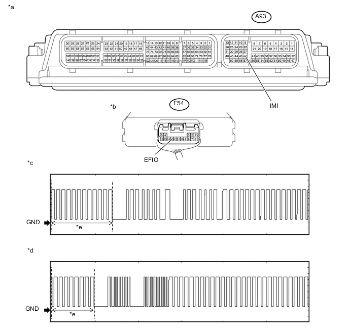
Text in Illustration *a Component with harness connected
(ECM)
*b Component with harness connected
(Transponder Key ECU Assembly)
*c Waveform 1 *d Waveform 2 *e Waveform A - - Measurement Condition Item Content Tester Connection A93-42 (IMI) - F54-13 (EFIO) Tool Setting 2 V/DIV., 500 ms./DIV. Condition Within 3 seconds after starter operates and initial combustion occurs, or within 3 seconds after ignition switch first turned to ON after battery disconnected and reconnected
-
-
for 2NR-FKE
-
Using an oscilloscope, check the waveform.
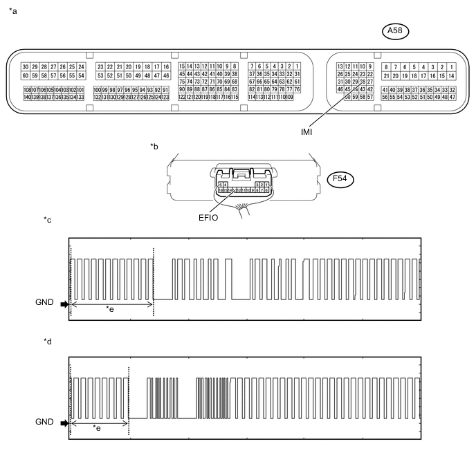
Text in Illustration *a Component with harness connected
(ECM)
*b Component with harness connected
(Transponder Key ECU Assembly)
*c Waveform 1 *d Waveform 2 *e Waveform A - - Measurement Condition Item Content Tester Connection A58-28 (IMI) - F54-13 (EFIO) Tool Setting 2 V/DIV., 500 ms./DIV. Condition Within 3 seconds after starter operates and initial combustion occurs, or within 3 seconds after ignition switch first turned to ON after battery disconnected and reconnected
-
-
for 1ND-TV without DPF
-
Using an oscilloscope, check the waveform.
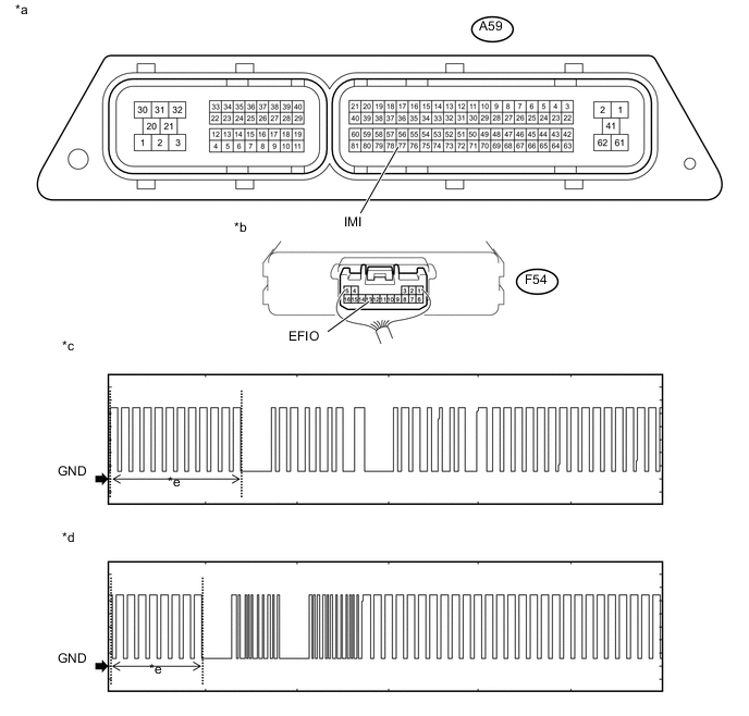
Text in Illustration *a Component with harness connected
(ECM)
*b Component with harness connected
(Transponder Key ECU Assembly)
*c Waveform 1 *d Waveform 2 *e Waveform A - - Measurement Condition Item Content Tester Connection A59-77 (IMI) - F54-13 (EFIO) Tool Setting 2 V/DIV., 500 ms./DIV. Condition Within 3 seconds after starter operates and initial combustion occurs, or within 3 seconds after ignition switch first turned to ON after battery disconnected and reconnected
-
-
for 1ND-TV with DPF
-
Using an oscilloscope, check the waveform.
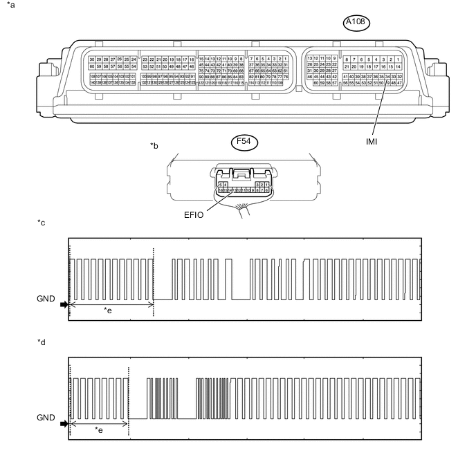
*a Component with harness connected
(ECM)
*b Component with harness connected
(Transponder Key ECU Assembly)
*c Waveform 1 *d Waveform 2 *e Waveform A - - Measurement Condition Item Content Tester Connection A108-34 (IMI) - F54-13 (EFIO) Tool Setting 2 V/DIV., 500 ms./DIV. Condition Within 3 seconds after starter operates and initial combustion occurs, or within 3 seconds after ignition switch first turned to ON after battery disconnected and reconnected
OK Waveform is output normally (refer to illustration). Result Result Proceed to Normal waveform A Waveform 1 or 2 (Waveform A) not output, or has abnormal wavelength or shape B -
B
CHECK HARNESS AND CONNECTOR (ECM - TRANSPONDER KEY ECU ASSEMBLY) Click here
A
-
-
CHECK ECM (TERMINAL IMO)
-
for 1KR-FE
-
Using an oscilloscope, check the waveform.
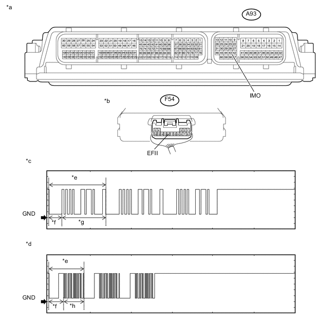
Text in Illustration *a Component with harness connected
(ECM)
*b Component with harness connected
(Transponder Key ECU Assembly)
*c Waveform 1 *d Waveform 2 *e Waveform B *f 160 ms *g 510 ms *h 270 ms Measurement Condition Item Content Tester Connection A93-43 (IMO) - F54-12 (EFII) Tool Setting 2 V/DIV., 500 ms./DIV. Condition Within 3 seconds after starter operates and initial combustion occurs, or within 3 seconds after ignition switch first turned to ON after battery disconnected and reconnected
-
-
for 2NR-FKE
-
Using an oscilloscope, check the waveform.
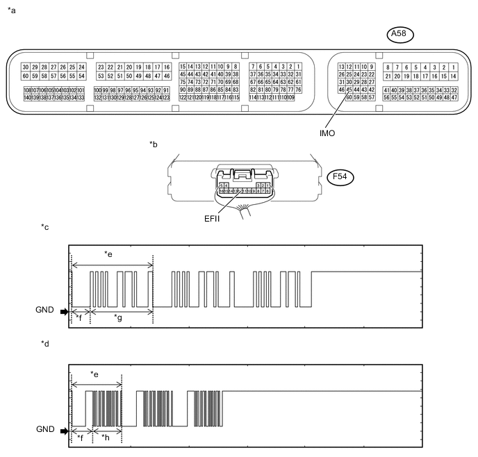
*a Component with harness connected
(ECM)
*b Component with harness connected
(Transponder Key ECU Assembly)
*c Waveform 1 *d Waveform 2 *e Waveform B *f 160 ms *g 510 ms *h 270 ms Measurement Condition Item Content Tester Connection A58-45 (IMO) - F54-12 (EFII) Tool Setting 2 V/DIV., 500 ms./DIV. Condition Within 3 seconds after starter operates and initial combustion occurs, or within 3 seconds after ignition switch first turned to ON after battery disconnected and reconnected
-
-
for 1ND-TV without DPF
-
Using an oscilloscope, check the waveform.
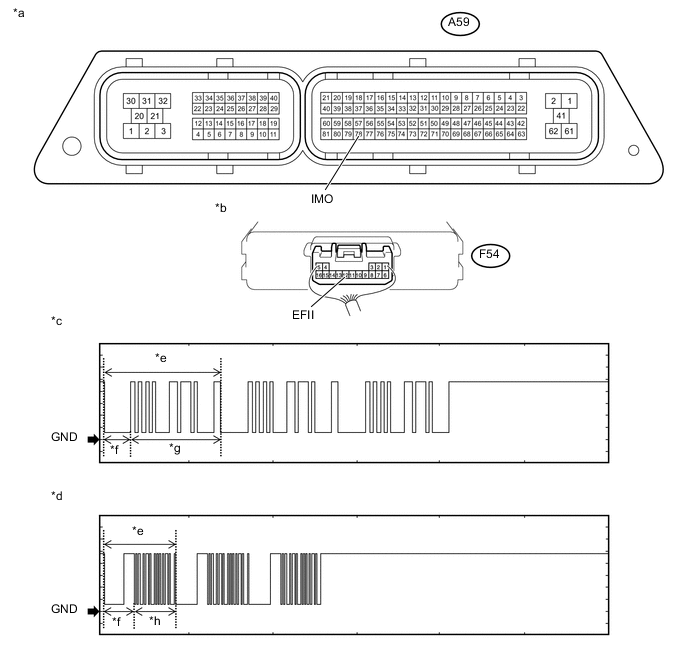
Text in Illustration *a Component with harness connected
(ECM)
*b Component with harness connected
(Transponder Key ECU Assembly)
*c Waveform 1 *d Waveform 2 *e Waveform B *f 160 ms *g 510 ms *h 270 ms Measurement Condition Item Content Tester Connection A59-78 (IMO) - F54-12 (EFII) Tool Setting 2 V/DIV., 500 ms./DIV. Condition Within 3 seconds after starter operates and initial combustion occurs, or within 3 seconds after ignition switch first turned to ON after battery disconnected and reconnected
-
-
for 1ND-TV with DPF
-
Using an oscilloscope, check the waveform.

Text in Illustration *a Component with harness connected
(ECM)
*b Component with harness connected
(Transponder Key ECU Assembly)
*c Waveform 1 *d Waveform 2 *e Waveform B *f 160 ms *g 510 ms *h 270 ms Measurement Condition Item Content Tester Connection A108-29 (IMO) - F54-12 (EFII) Tool Setting 2 V/DIV., 500 ms./DIV. Condition Within 3 seconds after starter operates and initial combustion occurs, or within 3 seconds after ignition switch first turned to ON after battery disconnected and reconnected
OK Waveform is output normally (refer to illustration). Result Result Proceed to Normal waveform A Waveform 1 or 2 (Waveform B) not output, or has abnormal wavelength or shape (for 1KR-FE) B Waveform 1 or 2 (Waveform B) not output, or has abnormal wavelength or shape (for 2NR-FKE) C Waveform 1 or 2 (Waveform B) not output, or has abnormal wavelength or shape (for 1ND-TV without DPF) D Waveform 1 or 2 (Waveform B) not output, or has abnormal wavelength or shape (for 1ND-TV with DPF) E -
B
REPLACE ECM Click here
C
REPLACE ECM Click here
D
REPLACE ECM Click here
E
REPLACE ECM Click here
A
-
-
CHECK ECM (TERMINAL IMI)
-
for 1KR-FE
-
Using an oscilloscope, check the waveform.
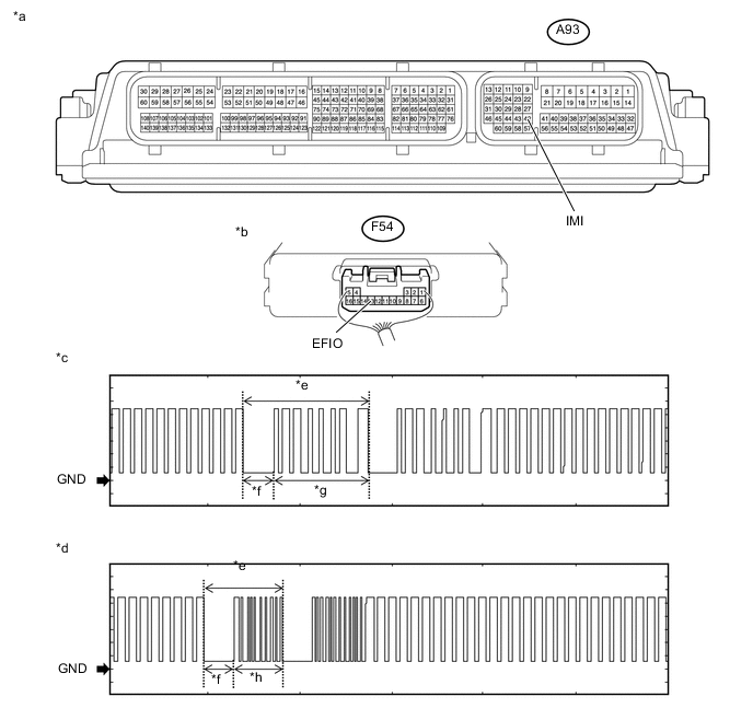
Text in Illustration *a Component with harness connected
(ECM)
*b Component with harness connected
(Transponder Key ECU Assembly)
*c Waveform 1 *d Waveform 2 *e Waveform B *f 160 ms *g 510 ms *h 270 ms Measurement Condition Item Content Tester Connection A93-42 (IMI) - F54-13 (EFIO) Tool Setting 2 V/DIV., 500 ms./DIV. Condition Within 3 seconds after starter operates and initial combustion occurs, or within 3 seconds after ignition switch first turned to ON after battery disconnected and reconnected
-
-
for 2NR-FKE
-
Using an oscilloscope, check the waveform.
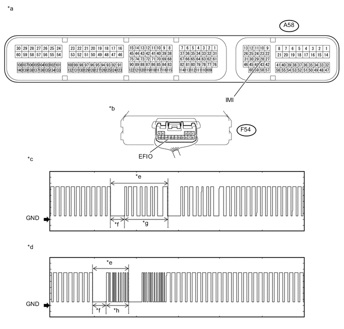
Text in Illustration *a Component with harness connected
(ECM)
*b Component with harness connected
(Transponder Key ECU Assembly)
*c Waveform 1 *d Waveform 2 *e Waveform B *f 160 ms *g 510 ms *h 270 ms Measurement Condition Item Content Tester Connection A58-28 (IMI) - F54-13 (EFIO) Tool Setting 2 V/DIV., 500 ms./DIV. Condition Within 3 seconds after starter operates and initial combustion occurs, or within 3 seconds after ignition switch first turned to ON after battery disconnected and reconnected
-
-
for 1ND-TV without DPF
-
Using an oscilloscope, check the waveform.
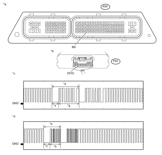
Text in Illustration *a Component with harness connected
(ECM)
*b Component with harness connected
(Transponder Key ECU Assembly)
*c Waveform 1 *d Waveform 2 *e Waveform B *f 160 ms *g 510 ms *h 270 ms Measurement Condition Item Content Tester Connection A59-77 (IMI) - F54-13 (EFIO) Tool Setting 2 V/DIV., 500 ms./DIV. Condition Within 3 seconds after starter operates and initial combustion occurs, or within 3 seconds after ignition switch first turned to ON after battery disconnected and reconnected
-
-
for 1ND-TV with DPF
-
Using an oscilloscope, check the waveform.
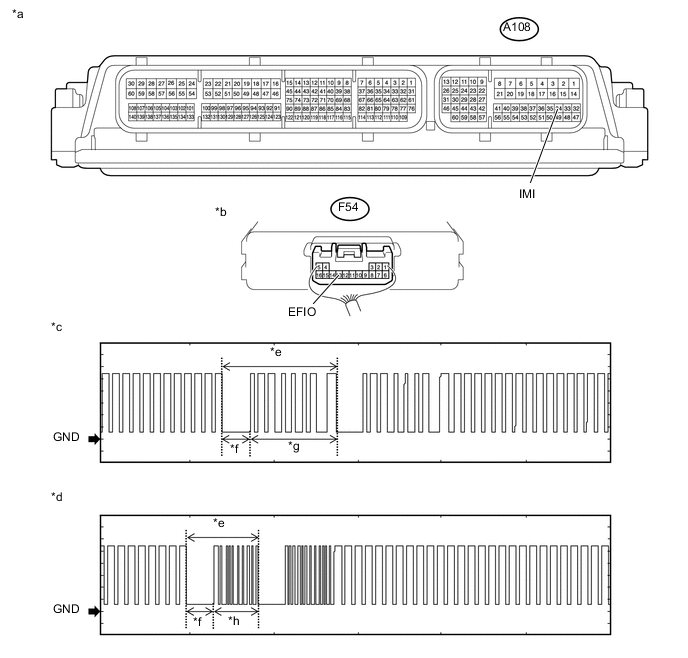
Text in Illustration *a Component with harness connected
(ECM)
*b Component with harness connected
(Transponder Key ECU Assembly)
*c Waveform 1 *d Waveform 2 *e Waveform B *f 160 ms *g 510 ms *h 270 ms Measurement Condition Item Content Tester Connection A108-34 (IMI) - F54-13 (EFIO) Tool Setting 2 V/DIV., 500 ms./DIV. Condition Within 3 seconds after starter operates and initial combustion occurs, or within 3 seconds after ignition switch first turned to ON after battery disconnected and reconnected
OK Waveform is output normally (refer to illustration). Result Result Proceed to Normal waveform A Waveform 1 or 2 (Waveform B) not output, or has abnormal wavelength or shape B -
B
REPLACE TRANSPONDER KEY ECU ASSEMBLY Click here
A
-
-
REGISTER ECU COMMUNICATION ID
-
Register the ECU communication ID (Refer to Service Bulletin).
NEXT
-
-
CHECK WHETHER ENGINE STARTS
-
Check that the engine starts with the key.
OK Engine starts normally.
OK
END (REGISTERED COMMUNICATION ID WAS DEFECTIVE)
NG
REPLACE TRANSPONDER KEY ECU ASSEMBLY Click here
-
-
CHECK HARNESS AND CONNECTOR (ECM - TRANSPONDER KEY ECU ASSEMBLY)
-
for 1KR-FE
-
Disconnect the A93 ECM connector.
-
Disconnect the F54 transponder key ECU assembly connector.
-
Measure the resistance according to the value(s) in the table below.
Standard Resistance Tester Connection Condition Specified Condition A93-42 (IMI) - F54-13 (EFIO) Always Below 1 Ω A93-42 (IMI) or F54-13 (EFIO) - Body ground Always 10 kΩ or higher
-
-
for 2NR-FKE
-
Disconnect the A58 ECM connector.
-
Disconnect the F54 transponder key ECU assembly connector.
-
Measure the resistance according to the value(s) in the table below.
Standard Resistance Tester Connection Condition Specified Condition A58-28 (IMI) - F54-13 (EFIO) Always Below 1 Ω A58-28 (IMI) or F54-13 (EFIO) - Body ground Always 10 kΩ or higher
-
-
for 1ND-TV without DPF
-
Disconnect the A59 ECM connector.
-
Disconnect the F54 transponder key ECU assembly connector.
-
Measure the resistance according to the value(s) in the table below.
Standard Resistance Tester Connection Condition Specified Condition A59-77 (IMI) - F54-13 (EFIO) Always Below 1 Ω A59-77 (IMI) or F54-13 (EFIO) - Body ground Always 10 kΩ or higher
-
-
for 1ND-TV with DPF
-
Disconnect the A108 ECM connector.
-
Disconnect the F54 transponder key ECU assembly connector.
-
Measure the resistance according to the value(s) in the table below.
Standard Resistance Tester Connection Condition Specified Condition A108-34 (IMI) - F54-13 (EFIO) Always Below 1 Ω A108-34 (IMI) or F54-13 (EFIO) - Body ground Always 10 kΩ or higher
-
NG
REPAIR OR REPLACE HARNESS OR CONNECTOR
OK
-
-
REPLACE TRANSPONDER KEY ECU ASSEMBLY
-
Replace the transponder key ECU assembly with a new one (Refer to Service Bulletin).
-
Check that the engine starts with the key.
OK Engine starts normally. Result Result Proceed to OK A NG (for 1KR-FE) B NG (for 2NR-FKE) C NG (for 1ND-TV with DPF) D NG (for 1ND-TV without DPF) E
A
END
B
GO TO SFI SYSTEM Click here
C
GO TO SFI SYSTEM Click here
D
GO TO ECD SYSTEM Click here
E
GO TO ECD SYSTEM Click here
-