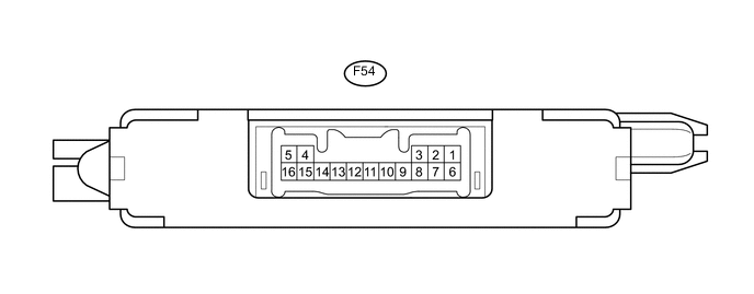
ENGINE IMMOBILISER SYSTEM(w/o Entry and Start System) TERMINALS OF ECU
-
CHECK TRANSPONDER KEY ECU ASSEMBLY
-
Disconnect the F54 transponder key ECU assembly connector.
-
Measure the resistance and voltage according to the value(s) in the table below.
Terminal No. (Symbol) Input/Output Wiring Color Terminal Description Condition Specified Condition Related Data List Item/DTC F54-5 (GND) - Body ground - BR - Body ground Ground Always Below 1 Ω - F54-1 (+B) - F54-5 (GND) Input Y - BR Battery Always 11 to 14 V +B F54-2 (IG) - F54-5 (GND) Input P - BR Ignition switch Ignition switch off Below 1 V IG SW Ignition switch ON 11 to 14 V F54-3 (KSW) - F54-5 (GND) Input BE - BR Unlock warning switch No key in ignition key cylinder 10 kΩ or higher Key SW/B2780 Key inserted in ignition key cylinder Below 1 Ω -
Reconnect the F54 transponder key ECU connector.
-
Measure the resistance and voltage, and check for pulses according to the value(s) in the table below.
Terminal No. (Symbol) Input/Output Wiring Color Terminal Description Condition Specified Condition Related Data List Item/DTC F54-9 (D) - F54-5 (GND) Input/Output B - BR DLC3 communication Without communication Below 1 V - During communication Pulse generation F54-4 (ANT1) - F54-5 (GND) Input/Output GR - BR Transponder key amplifier power source No key in ignition key cylinder 4 to 6 V - Within 3 seconds of inserting key into ignition key cylinder Pulse generation
(See waveform 1)
F54-15 (ANT2) - F54-5 (GND) Input/Output L - BR Transponder key amplifier communication signal No key in ignition key cylinder 4 to 6 V - Within 3 seconds of inserting key into ignition key cylinder Pulse generation
(See waveform 2)
F54-13 (EFIO) - F54-5 (GND) Input R - BR ECM output signal Ignition switch off Below 1 V E/G Start Permission Within 3 seconds of starter operation and initial combustion, or within 3 seconds of ignition switch first being turned to ON after cable disconnected and reconnected to negative (-) battery terminal Pulse generation
(See waveform 3)
F54-12 (EFII) - F54-5 (GND) Output LG - BR ECM input signal Within 3 seconds of starter operation and initial combustion, or within 3 seconds of ignition switch first being turned to ON after cable disconnected and reconnected to negative (-) battery terminal Pulse generation
(See waveform 4)
E/G Start Permission If the result is not as specified, the transponder key ECU assembly may be malfunctioning.
-
Using an oscilloscope, check the waveform.
-
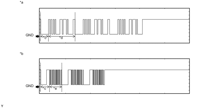
Waveform 1 (Reference)
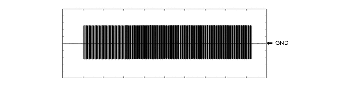
Measurement Condition Item Content Tester Connection F54-4 (ANT1) - F54-5 (GND) Tool Setting 20 V/DIV., 2 s./DIV. Condition Within 3 seconds of inserting key into ignition key cylinder -
Waveform 2 (Reference)
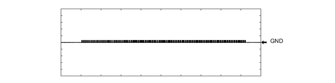
Measurement Condition Item Content Tester Connection F54-15 (ANT2) - F54-5 (GND) Tool Setting 20 V/DIV., 2 s./DIV. Condition Within 3 seconds of inserting key into ignition key cylinder -
Waveform 3 (Reference)
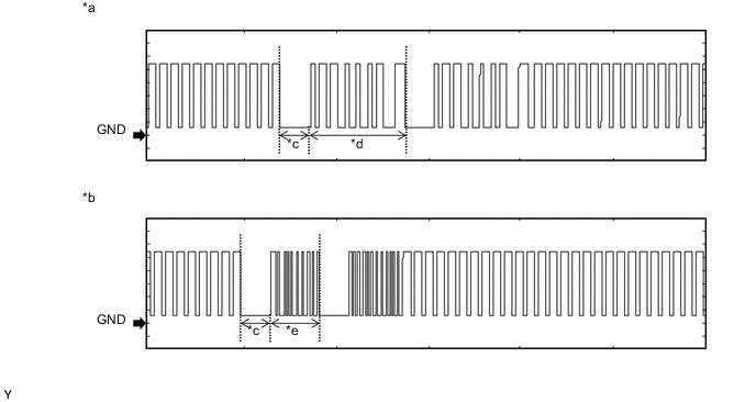
Text in Illustration *a Waveform A *b Waveform B *c Approximately 160 ms *d Approximately 510 ms *e Approximately 270 ms - - Measurement Condition Item Content Tester Connection F54-13 (EFIO) - F54-5 (GND) Tool Setting 2 V/DIV., 500 ms./DIV. Condition Within 3 seconds of starter operation and initial combustion, or within 3 seconds of ignition switch first being turned to ON after cable disconnected and reconnected to negative (-) battery terminal -
Waveform 4 (Reference)

Text in Illustration *a Waveform A *b Waveform B *c Approximately 160 ms *d Approximately 510 ms *e Approximately 270 ms - - Measurement Condition Item Content Tester Connection F54-12 (EFII) - F54-5 (GND) Tool Setting 2 V/DIV., 500 ms./DIV. Condition Within 3 seconds of starter operation and initial combustion, or within 3 seconds of ignition switch first being turned to ON after cable disconnected and reconnected to negative (-) battery terminal
-
-
-
CHECK ECM (for 1KR-FE)
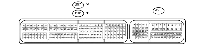
Text in Illustration *A for LHD *B for RHD
-
Measure the voltage and check for pulses according to the value(s) in the table below.
Terminal No. (Symbol) Input/Output Wiring Color Terminal Description Condition Specified Condition Related Data List Item/DTC A93-4 (E1) - Body ground - W-B - Body ground Ground Always Below 1 Ω - A93-15 (BATT) - A93-4 (E1) Input V - W-B +B power supply Always 11 to 14 V - A93-1 (+B1) - A93-4 (E1) Input B - W-B +B power supply Ignition switch ON 11 to 14 V - A93-2 (+B) - A93-4 (E1) Input B - W-B +B power supply Ignition switch ON 11 to 14 V - A93-43 (IMO) - A93-4 (E1) Input W - W-B Transponder key ECU assembly communication input Ignition switch off 11 to 14 V - Transponder key ECU assembly communication input Within 3 seconds after starter operates and initial combustion occurs, or within 3 seconds after ignition switch first turned to ON after battery disconnected and connected. Pulse generation
(See waveform 1)
- A93-42 (IMI) - A93-4 (E1) Output G - W-B Transponder key ECU assembly communication output Ignition switch off 11 to 14 V - Transponder key ECU assembly communication output Within 3 seconds after starter operates and initial combustion occurs, or within 3 seconds after ignition switch first turned to ON after battery disconnected and connected. Pulse generation
(See waveform 2)
- -
Inspect using an oscilloscope.
-
Waveform 1 (Reference)

Text in Illustration *a Waveform A *b Waveform B *c Approximately 160 ms *d Approximately 510 ms *e Approximately 270 ms - - Measurement Condition Item Content Tester Connection A93-43 (IMO) - A93-4 (E1) Tool Setting 2 V/DIV., 500 ms./DIV. Condition Within 3 seconds after starter operates and initial combustion occurs, or within 3 seconds after ignition switch first turned to ON after battery disconnected and reconnected -
Waveform 2 (Reference)

Text in Illustration *a Waveform A *b Waveform B *c Approximately 160 ms *d Approximately 510 ms *e Approximately 270 ms - - Measurement Condition Item Content Tester Connection A93-42 (IMI) - A93-4 (E1) Tool Setting 2 V/DIV., 500 ms./DIV. Condition Within 3 seconds after starter operates and initial combustion occurs, or within 3 seconds after ignition switch first turned to ON after battery disconnected and reconnected
-
-
-
CHECK ECM (for 2NR-FKE)
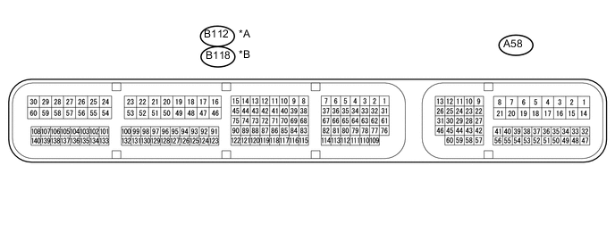
Text in Illustration *A for LHD *B for RHD
-
Measure the voltage and check for pulses according to the value(s) in the table below.
for LHD Terminal No. (Symbol) Input/Output Wiring Color Terminal Description Condition Specified Condition Related Data List Item/DTC B112-59 (E1) - Body ground - W-B - Body ground Ground Always Below 1 Ω - A58-1 (BATT) - B112-59 (E1) Input Y - W-B +B power supply Always 11 to 14 V - A58-3 (+B2) - B112-59 (E1) Input B - W-B +B power supply Ignition switch ON 11 to 14 V - A58-2 (+B) - B112-59 (E1) Input B - W-B +B power supply Ignition switch ON 11 to 14 V - A58-45 (IMO) - B112-59 (E1) Input W - W-B Transponder key ECU assembly communication input Ignition switch off 11 to 14 V - Transponder key ECU assembly communication input Within 3 seconds after starter operates and initial combustion occurs, or within 3 seconds after ignition switch first turned to ON after battery disconnected and connected. Pulse generation
(See waveform 1)
- A58-28 (IMI) - B112-59 (E1) Output G - W-B Transponder key ECU assembly communication output Ignition switch off 11 to 14 V - Transponder key ECU assembly communication output Within 3 seconds after starter operates and initial combustion occurs, or within 3 seconds after ignition switch first turned to ON after battery disconnected and connected. Pulse generation
(See waveform 2)
- for RHD Terminal No. (Symbol) Input/Output Wiring Color Terminal Description Condition Specified Condition Related Data List Item/DTC B118-59 (E1) - Body ground - W-B - Body ground Ground Always Below 1 Ω - A58-1 (BATT) - B118-59 (E1) Input Y - W-B +B power supply Always 11 to 14 V - A58-3 (+B2) - B118-59 (E1) Input B - W-B +B power supply Ignition switch ON 11 to 14 V - A58-2 (+B) - B118-59 (E1) Input B - W-B +B power supply Ignition switch ON 11 to 14 V - A58-45 (IMO) - B118-59 (E1) Input W - W-B Transponder key ECU assembly communication input Ignition switch off 11 to 14 V - Transponder key ECU assembly communication input Within 3 seconds after starter operates and initial combustion occurs, or within 3 seconds after ignition switch first turned to ON after battery disconnected and connected. Pulse generation
(See waveform 1)
- A58-28 (IMI) - B118-59 (E1) Output G - W-B Transponder key ECU assembly communication output Ignition switch off 11 to 14 V - Transponder key ECU assembly communication output Within 3 seconds after starter operates and initial combustion occurs, or within 3 seconds after ignition switch first turned to ON after battery disconnected and connected. Pulse generation
(See waveform 2)
- -
Inspect using an oscilloscope.
-
Waveform 1 (Reference)

Text in Illustration *a Waveform A *b Waveform B *c Approximately 160 ms *d Approximately 510 ms *e Approximately 270 ms - - Measurement Condition Item Content Tester Connection A58-45 (IMO) - B112-59 (E1)*1
A58-45 (IMO) - B118-59 (E1)*2
Tool Setting 2 V/DIV., 500 ms./DIV. Condition Within 3 seconds after starter operates and initial combustion occurs, or within 3 seconds after ignition switch first turned to ON after battery disconnected and reconnected
-
*1: for LHD
-
*2: for RHD
-
-
Waveform 2 (Reference)

Text in Illustration *a Waveform A *b Waveform B *c Approximately 160 ms *d Approximately 510 ms *e Approximately 270 ms - - Measurement Condition Item Content Tester Connection A58-28 (IMI) - B112-59 (E1)*1
A58-28 (IMI) - B118-59 (E1)*2
Tool Setting 2 V/DIV., 500 ms./DIV. Condition Within 3 seconds after starter operates and initial combustion occurs, or within 3 seconds after ignition switch first turned to ON after battery disconnected and reconnected
-
*1: for LHD
-
*2: for RHD
-
-
-
-
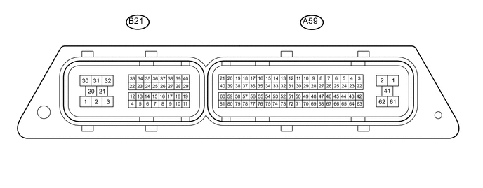
CHECK ECM (for 1ND-TV without DPF)
-
Measure the voltage and check for pulses according to the value(s) in the table below.
Terminal No. (Symbol) Input/Output Wiring Color Terminal Description Condition Specified Condition Related Data List Item/DTC A59-2 (E1) - Body ground - W-B - Body ground Ground Always Below 1 Ω - A59-23 (BATT) - A59-2 (E1) Input V - W-B +B power supply Always 11 to 14 V - A59-61 (+B2) - A59-2 (E1) Input B - W-B +B power supply Ignition switch ON 11 to 14 V - A59-1 (+B) - A59-2 (E1) Input B - W-B +B power supply Ignition switch ON 11 to 14 V - A59-78 (IMO) - A59-2 (E1) Input W - W-B Transponder key ECU assembly communication input Ignition switch off 11 to 14 V - Transponder key ECU assembly communication input Within 3 seconds after starter operates and initial combustion occurs, or within 3 seconds after ignition switch first turned to ON after battery disconnected and connected. Pulse generation
(See waveform 1)
- A59-77 (IMI) - A59-2 (E1) Output G - W-B Transponder key ECU assembly communication output Ignition switch off 11 to 14 V - Transponder key ECU assembly communication output Within 3 seconds after starter operates and initial combustion occurs, or within 3 seconds after ignition switch first turned to ON after battery disconnected and connected. Pulse generation
(See waveform 2)
- -
Inspect using an oscilloscope.
-
Waveform 1 (Reference)
Text in Illustration *a Waveform A *b Waveform B *c Approximately 160 ms *d Approximately 510 ms *e Approximately 270 ms - - Measurement Condition Item Content Tester Connection A59-78 (IMO) - A59-2 (E1) Tool Setting 2 V/DIV., 500 ms./DIV. Condition Within 3 seconds after starter operates and initial combustion occurs, or within 3 seconds after ignition switch first turned to ON after battery disconnected and reconnected -
Waveform 2 (Reference)

Text in Illustration *a Waveform A *b Waveform B *c Approximately 160 ms *d Approximately 510 ms *e Approximately 270 ms - - Measurement Condition Item Content Tester Connection A59-77 (IMI) - A59-2 (E1) Tool Setting 2 V/DIV., 500 ms./DIV. Condition Within 3 seconds after starter operates and initial combustion occurs, or within 3 seconds after ignition switch first turned to ON after battery disconnected and reconnected
-
-
-
CHECK ECM (for 1ND-TV with DPF)
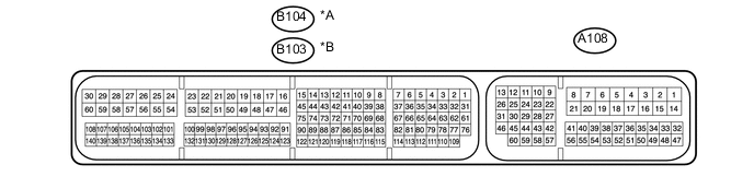
Text in Illustration *A for LHD *B for RHD
-
Measure the voltage and check for pulses according to the value(s) in the table below.
Terminal No. (Symbol) Input/Output Wiring Color Terminal Description Condition Specified Condition Related Data List Item/DTC A108-4 (E1) - Body ground - W-B - Body ground Ground Always Below 1 Ω - A108-15 (BATT) - A108-4 (E1) Input V - W-B +B power supply Always 11 to 14 V - A108-14 (+B2) - A108-4 (E1) Input B - W-B +B power supply Ignition switch ON 11 to 14 V - A108-2 (+B) - A108-4 (E1) Input B - W-B +B power supply Ignition switch ON 11 to 14 V - A108-1 (+B3) - A108-4 (E1) Input B - W-B +B power supply Ignition switch ON 11 to 14 V - A108-29 (IMO) - A108-4 (E1) Input W - W-B Transponder key ECU assembly communication input Ignition switch off 11 to 14 V - Transponder key ECU assembly communication input Within 3 seconds after starter operates and initial combustion occurs, or within 3 seconds after ignition switch first turned to ON after battery disconnected and connected. Pulse generation
(See waveform 1)
- A108-34 (IMI) - A108-4 (E1) Output G - W-B Transponder key ECU assembly communication output Ignition switch off 11 to 14 V - Transponder key ECU assembly communication output Within 3 seconds after starter operates and initial combustion occurs, or within 3 seconds after ignition switch first turned to ON after battery disconnected and connected. Pulse generation
(See waveform 2)
- -
Inspect using an oscilloscope.
-
Waveform 1 (Reference)
Text in Illustration *a Waveform A *b Waveform B *c Approximately 160 ms *d Approximately 510 ms *e Approximately 270 ms - - Measurement Condition Item Content Tester Connection A108-29 (IMO) - A108-4 (E1) Tool Setting 2 V/DIV., 500 ms./DIV. Condition Within 3 seconds after starter operates and initial combustion occurs, or within 3 seconds after ignition switch first turned to ON after battery disconnected and reconnected -
Waveform 2 (Reference)
Text in Illustration *a Waveform A *b Waveform B *c Approximately 160 ms *d Approximately 510 ms *e Approximately 270 ms - - Measurement Condition Item Content Tester Connection A108-34 (IMI) - A108-4 (E1) Tool Setting 2 V/DIV., 500 ms./DIV. Condition Within 3 seconds after starter operates and initial combustion occurs, or within 3 seconds after ignition switch first turned to ON after battery disconnected and reconnected
-
-