ENGINE IMMOBILISER SYSTEM(w/o Entry and Start System) TERMINALS OF ECU
-
CHECK TRANSPONDER KEY AMPLIFIER

-
Measure the resistance and voltage, and check for pulses according to the value(s) in the table below.
Terminal No. (Symbol) Input/Output Wiring Color Terminal Description Condition Specified Condition Related Data List Item/DTC F55-7 (AGND) - Body ground - GR - Body ground Ground Always Below 1 Ω - F55-1 (VC5) - F55-7 (AGND) Input P - GR Transponder key amplifier power supply No key in ignition key cylinder Below 1 V - F55-4 (CODE) - F55-7 (AGND) Output G - GR Demodulated signal of key code data No key in ignition key cylinder Below 1 V - F55-5 (TXCT) - F55-7 (AGND) Input L - GR Key code output signal No key in ignition key cylinder Below 1 V - -
Check for pulses according to the value(s) in the table below.
Terminal No. (Symbol) Input/Output Wiring Color Terminal Description Condition Specified Condition Related Data List Item/DTC F55-1 (VC5) - F55-7 (AGND) Input P - GR Transponder key amplifier power supply Key inserted in ignition key cylinder Pulse generation
(See waveform 1)
-
BCC Malfunction
-
Abnormal Status
-
Different Encrypt Code
-
Different Serial Number
(If immobiliser key code certification communication is not performed correctly, the malfunction may be indicated by one or more of the Data List items listed above)
F55-4 (CODE) - F55-7 (AGND) Output G - GR Demodulated signal of key code data Key inserted in ignition key cylinder Pulse generation
(See waveform 2)
F55-5 (TXCT) - F55-7 (AGND) Input L - GR Key code output signal Key inserted in ignition key cylinder Pulse generation
(See waveform 3)
-
-
Inspect using an oscilloscope.
Note
The waveform shown in the illustration is an example for reference only. Noise, chattering, etc. are not shown.
-
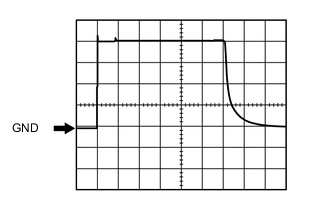
Waveform 1 (Reference)
Measurement Condition Item Content Tester Connection F55-1 (VC5) - F55-7 (AGND) Tool Setting 1 V/DIV., 20 ms./DIV. Condition Key inserted in ignition key cylinder -
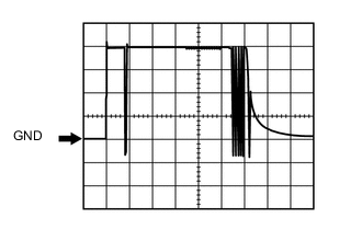
Waveform 2 (Reference)
Measurement Condition Item Content Tester Connection F55-4 (CODE) - F55-7 (AGND) Tool Setting 1 V/DIV., 20 ms./DIV. Condition Key inserted in ignition key cylinder -

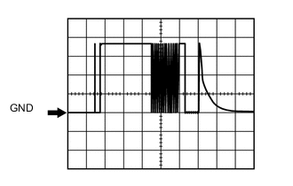
Waveform 3 (Reference)
Measurement Condition Item Content Tester Connection F55-5 (TXCT) - F55-7 (AGND) Tool Setting 1 V/DIV., 20 ms./DIV. Condition Key inserted in ignition key cylinder
-
-
-
CHECK TRANSPONDER KEY ECU ASSEMBLY
-
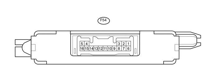
Disconnect the F54 transponder key ECU assembly connector.
-
Measure the resistance and voltage according to the value(s) in the table below.
Terminal No. (Symbol) Input/Output Wiring Color Terminal Description Condition Specified Condition Related Data List Item/DTC F54-16 (GND) - Body ground - BR - Body ground Ground Always Below 1 Ω - F54-1 (+B) - F54-16 (GND) Input Y - BR Battery Always 11 to 14 V +B F54-2 (IG) - F54-16 (GND) Input P - BR Ignition switch Ignition switch off Below 1 V IG SW Ignition switch ON 11 to 14 V F54-3 (KSW) - F54-16 (GND) Input BE - BR Unlock warning switch No key in ignition key cylinder 10 kΩ or higher Key SW/B2780 Key inserted in ignition key cylinder Below 1 Ω -
Reconnect the F54 transponder key ECU connector.
-
Measure the resistance and voltage, and check for pulses according to the value(s) in the table below.
Terminal No. (Symbol) Input/Output Wiring Color Terminal Description Condition Specified Condition Related Data List Item/DTC F54-14 (VC5) - F54-16 (GND) Input P - BR Transponder key amplifier power supply No key in ignition key cylinder Below 1 V
-
BCC Malfunction
-
Abnormal Status
-
Different Encrypt Code
-
Different Serial Number
(If immobiliser key code certification communication is not performed correctly, the malfunction may be indicated by one or more of the Data List items listed above)
Key inserted in ignition key cylinder Pulse generation
(See waveform 1)
F54-4 (TXCT) - F54-16 (GND) Input L - BR Key code output signal No key in ignition key cylinder Below 1 V Key inserted in ignition key cylinder Pulse generation
(See waveform 2)
F54-15 (CODE) - F54-16 (GND) Output G - BR Demodulated signal of key code data No key in ignition key cylinder Below 1 V Key inserted in ignition key cylinder Pulse generation
(See waveform 3)
F54-13 (EFIO) - F54-16 (GND) Input R - BR ECM output signal Ignition switch off Below 1 V E/G Start Permission Ignition switch ON Pulse generation
(See waveform 4)
F54-12 (EFII) - F54-16 (GND) Output LG - BR ECM input signal Within 3 seconds after starter operates and initial combustion occurs, or within 3 seconds after ignition switch first turned to ON after battery disconnected and reconnected Pulse generation
(See waveform 5)
E/G Start Permission F54-9 (D) - F54-16 (GND) Input/Output B - BR Diagnosis tester communication Always Pulse generation - F54-5 (AGND) - Body ground - GR - Body ground Transponder key amplifier ground Always Below 1 Ω - -
-
Inspect using an oscilloscope.
Note
The waveform shown in the illustration is an example for reference only. Noise, chattering, etc. are not shown.
-

Waveform 1 (Reference)
Measurement Condition Item Content Tester Connection F54-14 (VC5) - F54-16 (GND) Tool Setting 1 V/DIV., 20 ms./DIV. Condition Key inserted in ignition key cylinder -
Waveform 2 (Reference)
Measurement Condition Item Content Tester Connection F54-4 (TXCT) - F54-16 (GND) Tool Setting 1 V/DIV., 20 ms./DIV. Condition Key inserted in ignition key cylinder -

Waveform 3 (Reference)
Measurement Condition Item Content Tester Connection F54-15 (CODE) - F54-16 (GND) Tool Setting 1 V/DIV., 20 ms./DIV. Condition Key inserted in ignition key cylinder -
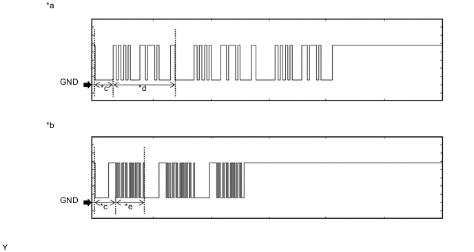
Waveform 4 (Reference)

Text in Illustration *a Waveform A *b Waveform B *c Approximately 160 ms *d Approximately 510 ms *e Approximately 270 ms - - Measurement Condition Item Content Tester Connection F54-13 (EFIO) - F54-16 (GND) Tool Setting 2 V/DIV., 500 ms./DIV. Condition Ignition switch ON -
Waveform 5 (Reference)

Text in Illustration *a Waveform A *b Waveform B *c Approximately 160 ms *d Approximately 510 ms *e Approximately 270 ms - - Measurement Condition Item Content Tester Connection F54-12 (EFII) - F54-16 (GND) Tool Setting 2 V/DIV., 500 ms./DIV. Condition Within 3 seconds after starter operates and initial combustion occurs, or within 3 seconds after ignition switch first turned to ON after battery disconnected and reconnected
-
-
-
CHECK ECM (for 1KR-FE)
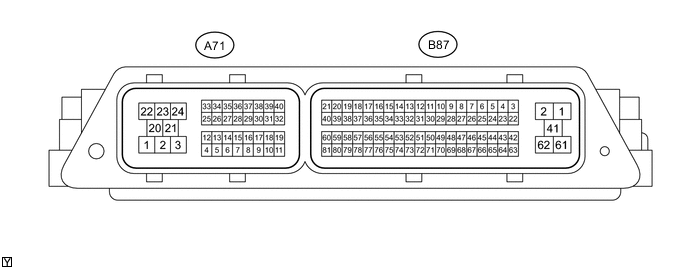
-
Measure the voltage and check for pulses according to the value(s) in the table below.
Terminal No. (Symbol) Input/Output Wiring Color Terminal Description Condition Specified Condition Related Data List Item/DTC A71-1 (E1) - Body ground - W-B - Body ground Ground Always Below 1 Ω - A71-22 (BATT) - A71-1 (E1) Input V - W-B +B power supply Always 11 to 14 V - A71-23 (+B2) - A71-1 (E1) Input B - W-B +B power supply Ignition switch ON 11 to 14 V - A71-24 (+B) - A71-1 (E1) Input B - W-B +B power supply Ignition switch ON 11 to 14 V - A71-6 (IMO) - A71-1 (E1) Input W - W-B Transponder key ECU assembly communication input Ignition switch off 11 to 14 V - Transponder key ECU assembly communication input Within 3 seconds after starter operates and initial combustion occurs, or within 3 seconds after ignition switch first turned to ON after battery disconnected and connected. Pulse generation
(See waveform 1)
- A71-39 (IMI) - A71-1 (E1) Output G - W-B Transponder key ECU assembly communication output Ignition switch off 11 to 14 V - Transponder key ECU assembly communication output Ignition switch ON Pulse generation
(See waveform 2)
- -
Inspect using an oscilloscope.
-
Waveform 1 (Reference)

Text in Illustration *a Waveform A *b Waveform B *c Approximately 160 ms *d Approximately 510 ms *e Approximately 270 ms - - Measurement Condition Item Content Tester Connection A71-6 (IMO) - A71-1 (E1) Tool Setting 2 V/DIV., 500 ms./DIV. Condition Within 3 seconds after starter operates and initial combustion occurs, or within 3 seconds after ignition switch first turned to ON after battery disconnected and reconnected -
Waveform 2 (Reference)

Text in Illustration *a Waveform A *b Waveform B *c Approximately 160 ms *d Approximately 510 ms *e Approximately 270 ms - - Measurement Condition Item Content Tester Connection A71-39 (IMI) - A71-1 (E1) Tool Setting 2 V/DIV., 500 ms./DIV. Condition Ignition switch ON
-
-
-
CHECK ECM (for 1NR-FE)
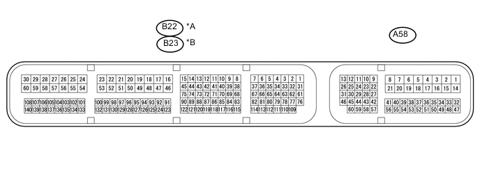
Text in Illustration *A for LHD *B for RHD
-
Measure the voltage and check for pulses according to the value(s) in the table below.
for LHD Terminal No. (Symbol) Input/Output Wiring Color Terminal Description Condition Specified Condition Related Data List Item/DTC B22-16 (E1) - Body ground - W-B - Body ground Ground Always Below 1 Ω - A58-1 (BATT) - B22-16 (E1) Input Y - W-B +B power supply Always 11 to 14 V - A58-3 (+B2) - B22-16 (E1) Input L - W-B +B power supply Ignition switch ON 11 to 14 V - A58-2 (+B) - B22-16 (E1) Input B - W-B +B power supply Ignition switch ON 11 to 14 V - A58-29 (IMO) - B22-16 (E1) Input W - W-B Transponder key ECU assembly communication input Ignition switch off 11 to 14 V - Transponder key ECU assembly communication input Within 3 seconds after starter operates and initial combustion occurs, or within 3 seconds after ignition switch first turned to ON after battery disconnected and connected. Pulse generation
(See waveform 1)
- A58-28 (IMI) - B22-16 (E1) Output G - W-B Transponder key ECU assembly communication output Ignition switch off 11 to 14 V - Transponder key ECU assembly communication output Ignition switch ON Pulse generation
(See waveform 2)
- for RHD Terminal No. (Symbol) Input/Output Wiring Color Terminal Description Condition Specified Condition Related Data List Item/DTC B23-16 (E1) - Body ground - W-B - Body ground Ground Always Below 1 Ω - A58-1 (BATT) - B23-16 (E1) Input Y - W-B +B power supply Always 11 to 14 V - A58-3 (+B2) - B23-16 (E1) Input L - W-B +B power supply Ignition switch ON 11 to 14 V - A58-2 (+B) - B23-16 (E1) Input B - W-B +B power supply Ignition switch ON 11 to 14 V - A58-29 (IMO) - B23-16 (E1) Input W - W-B Transponder key ECU assembly communication input Ignition switch off 11 to 14 V - Transponder key ECU assembly communication input Within 3 seconds after starter operates and initial combustion occurs, or within 3 seconds after ignition switch first turned to ON after battery disconnected and connected. Pulse generation
(See waveform 1)
- A58-28 (IMI) - B23-16 (E1) Output G - W-B Transponder key ECU assembly communication output Ignition switch off 11 to 14 V - Transponder key ECU assembly communication output Ignition switch ON Pulse generation
(See waveform 2)
- -
Inspect using an oscilloscope.
-
Waveform 1 (Reference)

Text in Illustration *a Waveform A *b Waveform B *c Approximately 160 ms *d Approximately 510 ms *e Approximately 270 ms - - Measurement Condition Item Content Tester Connection A58-29 (IMO) - B22-16 (E1)*1
A58-29 (IMO) - B23-16 (E1)*2
Tool Setting 2 V/DIV., 500 ms./DIV. Condition Within 3 seconds after starter operates and initial combustion occurs, or within 3 seconds after ignition switch first turned to ON after battery disconnected and reconnected
-
*1: for LHD
-
*2: for RHD
-
-
Waveform 2 (Reference)
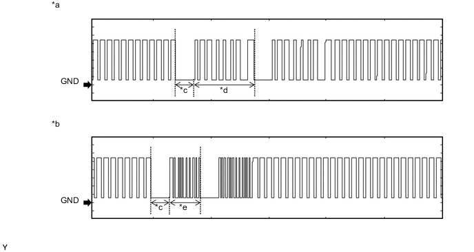
Text in Illustration *a Waveform A *b Waveform B *c Approximately 160 ms *d Approximately 510 ms *e Approximately 270 ms - - Measurement Condition Item Content Tester Connection A58-28 (IMI) - B22-16 (E1)*1
A58-28 (IMI) - B23-16 (E1)*2
Tool Setting 2 V/DIV., 500 ms./DIV. Condition Ignition switch ON
-
*1: for LHD
-
*2: for RHD
-
-
-
-
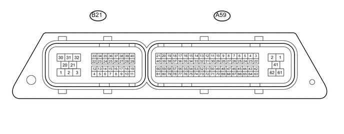
CHECK ECM (for 1ND-TV)
-
Measure the voltage and check for pulses according to the value(s) in the table below.
Terminal No. (Symbol) Input/Output Wiring Color Terminal Description Condition Specified Condition Related Data List Item/DTC A59-2 (E1) - Body ground - W-B - Body ground Ground Always Below 1 Ω - A59-23 (BATT) - A59-2 (E1) Input V - W-B +B power supply Always 11 to 14 V - A59-61 (+B2) - A59-2 (E1) Input B - W-B +B power supply Ignition switch ON 11 to 14 V - A59-1 (+B) - A59-2 (E1) Input B - W-B +B power supply Ignition switch ON 11 to 14 V - A59-78 (IMO) - A59-2 (E1) Input W - W-B Transponder key ECU assembly communication input Ignition switch off 11 to 14 V - Transponder key ECU assembly communication input Within 3 seconds after starter operates and initial combustion occurs, or within 3 seconds after ignition switch first turned to ON after battery disconnected and connected. Pulse generation
(See waveform 1)
- A59-77 (IMI) - A59-2 (E1) Output G - W-B Transponder key ECU assembly communication output Ignition switch off 11 to 14 V - Transponder key ECU assembly communication output Ignition switch ON Pulse generation
(See waveform 2)
- -
Inspect using an oscilloscope.
-
Waveform 1 (Reference)
Text in Illustration *a Waveform A *b Waveform B *c Approximately 160 ms *d Approximately 510 ms *e Approximately 270 ms - - Measurement Condition Item Content Tester Connection A59-78 (IMO) - A59-2 (E1) Tool Setting 2 V/DIV., 500 ms./DIV. Condition Within 3 seconds after starter operates and initial combustion occurs, or within 3 seconds after ignition switch first turned to ON after battery disconnected and reconnected -
Waveform 2 (Reference)

Text in Illustration *a Waveform A *b Waveform B *c Approximately 160 ms *d Approximately 510 ms *e Approximately 270 ms - - Measurement Condition Item Content Tester Connection A59-77 (IMI) - A59-2 (E1) Tool Setting 2 V/DIV., 500 ms./DIV. Condition Ignition switch ON
-
-