ENTRY AND START SYSTEM(for Start Function) Power Source Mode does not Change to ON (IG and ACC)
DESCRIPTION
If any of the following operations are performed, the certification ECU (smart key ECU assembly) receives a signal, and changes the power source mode.
-
With the electrical key transmitter sub-assembly in the cabin, the engine switch is pressed.
-
When the transmitter battery in the electrical key transmitter sub-assembly is depleted, touch the electrical key transmitter sub-assembly to the surface of the engine switch while depressing the brake pedal*1 or clutch pedal*2.
-
When the entry cancel function is set by customize operation, touch the electrical key transmitter sub-assembly to the surface of the engine switch while depressing the brake pedal*1 or clutch pedal*2.
-
*1: for CVT
-
*2: for Manual Transaxle
Tech Tips
When the battery cable is disconnected and reconnected, the power source returns to the mode it was in before the battery cable was disconnected.
| Problem Symptom | Data List Item | Active Test Item |
|---|---|---|
| Power source mode does not change to on (IG) or on (ACC) |
Power Source Control
Starting Control |
- |
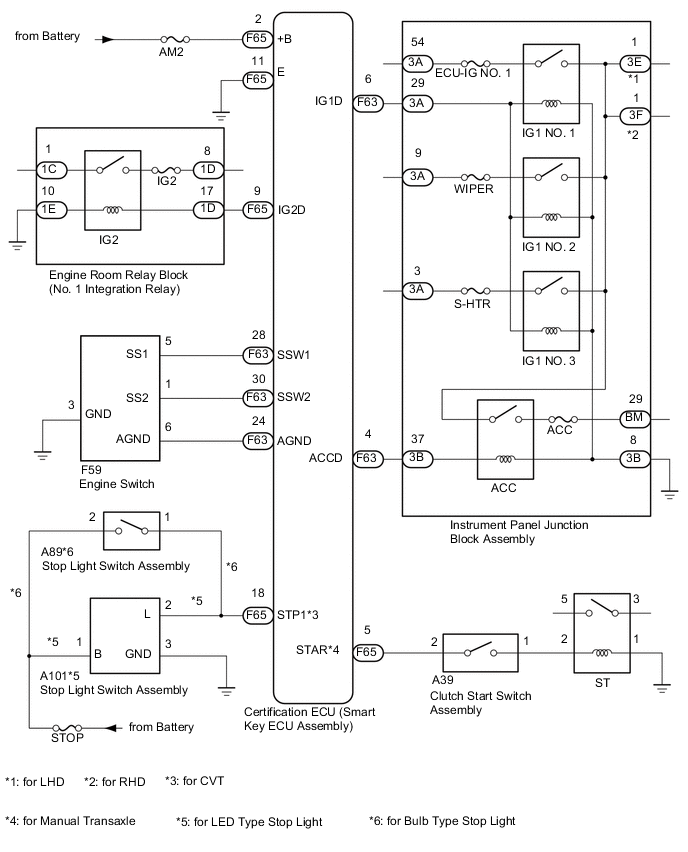
WIRING DIAGRAM
CAUTION / NOTICE / HINT
Note
-
When using the intelligent tester with the engine switch off to troubleshoot:
Connect the intelligent tester to the DLC3 and turn a courtesy light switch on and off at 1.5 second intervals until communication between the intelligent tester and vehicle begins.
-
The entry and start system uses multiplex communication. First perform the inspections in "How to Proceed with Troubleshooting" to confirm that there are no communication malfunctions before proceeding with troubleshooting Click here.
-
Before replacing the certification ECU (smart key ECU assembly), refer to the entry and start system (for Entry Function) Click here.
-
Make sure that no DTCs are output. If any DTCs are output, proceed to the Diagnostic Trouble Code Chart Click here.
-
If the entry and start system is disabled through the customize function, enable the system before performing troubleshooting Click here.
-
After completing repairs, confirm that the problem does not reoccur.
-
Inspect the fuses of circuits related to this system before performing the following inspection procedure.
PROCEDURE
-
CHECK WIRELESS DOOR LOCK CONTROL SYSTEM (OPERATION)
-
Check that the wireless door lock functions operate normally Click here.
OK Wireless door lock functions operate normally.
NG 
GO TO ENTRY AND START SYSTEM (ALL DOOR ENTRY LOCK/UNLOCK FUNCTIONS AND WIRELESS FUNCTIONS DO NOT OPERATE) Click here
OK 
-
-
CHECK HARNESS AND CONNECTOR (POWER SOURCE)
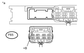
Text in Illustration *a Rear view of harness connected
(to Certification ECU (Smart Key ECU Assembly))
-
Disconnect the F65 certification ECU (smart key ECU assembly) connector.
-
Measure the voltage according to the value(s) in the table below.
Standard Voltage Tester Connection Condition Specified Condition F65-2 (+B) - Body ground Always 9.5 to 16 V
NG
REPAIR OR REPLACE HARNESS OR CONNECTOR IN CIRCUIT CONNECTED TO POWER SOURCE
OK
-
-
CHECK HARNESS AND CONNECTOR (GROUND)
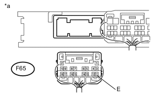
Text in Illustration *a Rear view of harness connected
(to Certification ECU (Smart Key ECU Assembly))
-
Disconnect the F65 certification ECU (smart key ECU assembly) connector.
-
Measure the resistance according to the value(s) in the table below.
Standard Resistance Tester Connection Condition Specified Condition F65-11 (E) - Body ground Always Below 1 Ω
NG
REPAIR OR REPLACE HARNESS OR CONNECTOR
OK
-
-
CHECK ENTRY AND START SYSTEM
-
Remove the battery of the electrical key transmitter sub-assembly Click here.
-
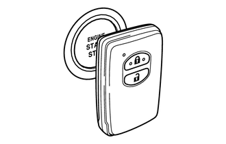
With the brake pedal*1 or clutch pedal*2 depressed, touch the electrical key transmitter sub-assembly to the engine switch while facing the logo side of the electrical key transmitter sub-assembly to the engine switch.
-
*1: for CVT
-
*2: for Manual Transaxle
-
-
When touching the logo of the electrical key transmitter sub-assembly to the engine switch, check whether the power source mode changes.
OK Power source mode changes. Tech Tips
If the power source mode changes, the cabin verification is malfunctioning.
Result Result Proceed to NG (Power source mode does not change) A OK (Power source mode changes) B
B 
READ VALUE USING INTELLIGENT TESTER (START SWITCH 1, 2) Click here
A
-
-
READ VALUE USING INTELLIGENT TESTER (STOP LIGHT SWITCH, NEUTRAL SW/CLUTCH SW)
-
for CVT
-
Connect the intelligent tester to the DLC3.
-
Turn the engine switch on (IG).
-
Turn the intelligent tester on.
-
Enter the following menus: Body / Power Source Control / Data List.
-
According to the display on the intelligent tester, read the Data List.
Power Source Control Tester Display Measurement Item/Range Normal Condition Diagnostic Note Stop Light Switch1 State of brake pedal / OFF or ON OFF: Brake pedal released
ON: Brake pedal depressed
-
Use this item to determine whether the stop light switch is malfunctioning.
-
The engine cannot be started when this item is "OFF".
-
When this item is malfunctioning, the engine can be started by pressing and holding the engine switch for a certain period of time.
OK ON (brake pedal depressed) and OFF (brake pedal released) appear on the screen according to the stop light switch condition. -
-
-
for Manual Transaxle
-
Connect the intelligent tester to the DLC3.
-
Turn the engine switch on (IG).
-
Turn the intelligent tester on.
-
Enter the following menus: Body / Power Source Control / Data List.
-
According to the display on the intelligent tester, read the Data List.
Power Source Control Tester Display Measurement Item/Range Normal Condition Diagnostic Note Neutral SW / Clutch SW State of clutch pedal / OFF or ON OFF: Clutch pedal released
ON: Clutch pedal depressed
-
Use this item to help determine if the clutch switch is malfunctioning.
-
The engine cannot be started when this item is "OFF".
OK ON (clutch pedal depressed) and OFF (clutch pedal released) appear on the screen according to the stop light switch condition. Result Result Proceed to OK A NG (for CVT) B NG (for Manual Transaxle) C -
-
B
SYSTEM CHECK Click here
C
INSPECT CLUTCH START SWITCH ASSEMBLY Click here
A
-
-
READ VALUE USING INTELLIGENT TESTER (POWER SUPPLY CONDITION)
-
Connect the intelligent tester to the DLC3.
-
Turn the engine switch on (IG).
-
Turn the intelligent tester on.
-
Enter the following menus: Body / Power Source Control / Data List.
-
According to the display on the intelligent tester, read the Data List.
Power Source Control Tester Display Measurement Item/Range Normal Condition Diagnostic Note Power Supply Condition Power Supply Condition / All OFF, IG ON or ACC ON, IG2 ON, ST ON, All OFF: Engine switch off (ACC and IG)
ACC ON: Engine switch on (ACC))
IG1 ON: Engine switch on (IG) (IG1 relay on)
IG2 ON: Engine switch on (IG) (IG2 relay on)
ST ON: Sending engine start request signal
Since IG1 ON and IG2 ON turn on at approximately the same time, IG1 ON may not be displayed (IG1 ON turns on for a very short time). OK Display changes according to the changes in the power source mode when the engine switch is pushed.
NG
CHECK FOR DTC Click here
OK
-
-
INSPECT CERTIFICATION ECU (SMART KEY ECU ASSEMBLY)
-
Connect the intelligent tester to the DLC3.
-
Turn the engine switch on (IG).
-
Turn the intelligent tester on.
-
Enter the following menus: Body / Power Source Control / Data List.
-
According to the display on the intelligent tester, read the Data List.
Power Source Control Tester Display Measurement Item/Range Normal Condition Diagnostic Note Power Supply Condition Power Supply Condition / All OFF, IG ON or ACC ON, IG2 ON, ST ON, All OFF: Engine switch off (ACC and IG)
ACC ON: Engine switch on (ACC))
IG1 ON: Engine switch on (IG) (IG1 relay on)
IG2 ON: Engine switch on (IG) (IG2 relay on)
ST ON: Sending engine start request signal
Since IG1 ON and IG2 ON turn on at approximately the same time, IG1 ON may not be displayed (IG1 ON turns on for a very short time). -
Measure the voltage according to the value(s) in the table below.
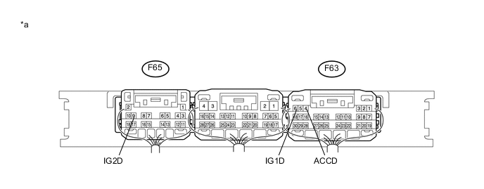
Text in Illustration *a Component with harness connected
(Certification ECU (Smart Key ECU Assembly))
- - Standard Voltage Tester Connection Switch Condition Specified Condition F63-6 (IG1D) - Body ground Engine switch off 1 V or less Engine switch on (ACC) 1 V or less Engine switch on (IG) 9 V or higher F65-9 (IG2D) - Body ground Engine switch off 1 V or less Engine switch on (ACC) 1 V or less Engine switch on (IG) 9 V or higher F63-4 (ACCD) - Body ground Engine switch off 1 V or less Engine switch on (ACC) 8.5 V or higher Engine switch on (IG) 8.5 V or higher
OK
CHECK RELAY CONTACT SIDE CIRCUIT Click here
NG
REPLACE CERTIFICATION ECU (SMART KEY ECU ASSEMBLY)
-
-
SYSTEM CHECK
-
Check the vehicle specifications.
Result Result Proceed to for LED Type Stop Light A for Bulb Type Stop Light B
B
INSPECT STOP LIGHT SWITCH ASSEMBLY Click here
A
-
-
CHECK HARNESS AND CONNECTOR (STOP LIGHT SWITCH ASSEMBLY - POWER SOURCE AND BODY GROUND)
-
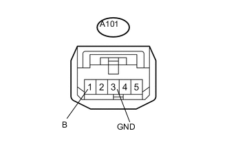
Text in Illustration *a Front view of wire harness connector
(to Stop Light Switch Assembly)
Disconnect the stop light switch assembly connector.
-
Measure the voltage and resistance according to the value(s) in the table below.
Standard Voltage Tester Connection Switch Condition Specified Condition A101-1 (B) - A101-3 (GND) Engine switch off 11 to 14 V Standard Resistance Tester Connection Condition Specified Condition A101-3 (GND) - Body ground Always Below 1 Ω
NG
REPAIR OR REPLACE HARNESS OR CONNECTOR
OK
-
-
INSPECT STOP LIGHT SWITCH ASSEMBLY
-
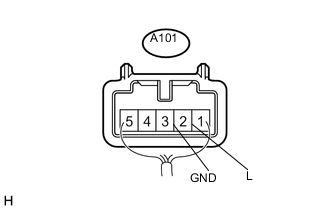
Text in Illustration *a Component with harness connected
(Stop Light Switch Assembly)
Reconnect the stop light switch assembly connector.
-
Measure the voltage according to the value(s) in the table below.
Standard Voltage Tester Connection Switch Condition Specified Condition A101-2 (L) - A101-3 (GND) Engine switch off, Brake pedal not depressed Below 1V A101-2 (L) - A101-3 (GND) Engine switch off, Brake pedal depressed 11 to 14 V
NG
REPLACE STOP LIGHT SWITCH ASSEMBLY Click here
OK
-
-
CHECK HARNESS AND CONNECTOR (CERTIFICATION ECU (SMART KEY ECU ASSEMBLY) - STOP LIGHT SWITCH ASSEMBLY)
-
Disconnect the F65 certification ECU (smart key ECU assembly) connector.
-
Disconnect the A101*1 or A89*2 stop light switch assembly connector.
-
*1: for LED Type Stop Light
-
*2: for Bulb Type Stop Light
-
-
Measure the resistance according to the value(s) in the table below.
Standard Resistance for LED Type Stop Light Tester Connection Condition Specified Condition F65-18 (STP1) - A101-2 (L) Always Below 1 Ω F65-18 (STP1) - Body ground Always 10 kΩ or higher for Bulb Type Stop Light Tester Connection Condition Specified Condition F65-18 (STP1) - A89-1 Always Below 1 Ω F65-18 (STP1) - Body ground Always 10 kΩ or higher -
Reconnect the A101*1 or A89*2 stop light switch assembly connector.
-
*1: for LED Type Stop Light
-
*2: for Bulb Type Stop Light
-
-
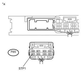
Text in Illustration *a Rear view of wire harness connector
(Certification ECU (Smart Key ECU Assembly))
Measure the voltage according to the value(s) in the table below.
Standard Voltage Tester Connection Condition Specified Condition F65-18 (STP1) - Body ground Brake pedal released Below 1 V Brake pedal depressed 9 V or higher
OK
REPLACE CERTIFICATION ECU (SMART KEY ECU ASSEMBLY)
NG
REPAIR OR REPLACE HARNESS OR CONNECTOR
-
-
INSPECT STOP LIGHT SWITCH ASSEMBLY
-
Inspect the stop light switch assembly Click here.
NG
REPLACE STOP LIGHT SWITCH ASSEMBLY Click here
OK
-
-
CHECK HARNESS AND CONNECTOR (CERTIFICATION ECU (SMART KEY ECU ASSEMBLY) - STOP LIGHT SWITCH ASSEMBLY)
-
Disconnect the F65 certification ECU (smart key ECU assembly) connector.
-
Disconnect the A101*1 or A89*2 stop light switch assembly connector.
-
*1: for LED Type Stop Light
-
*2: for Bulb Type Stop Light
-
-
Measure the resistance according to the value(s) in the table below.
Standard Resistance for LED Type Stop Light Tester Connection Condition Specified Condition F65-18 (STP1) - A101-2 (L) Always Below 1 Ω F65-18 (STP1) - Body ground Always 10 kΩ or higher for Bulb Type Stop Light Tester Connection Condition Specified Condition F65-18 (STP1) - A89-1 Always Below 1 Ω F65-18 (STP1) - Body ground Always 10 kΩ or higher -
Reconnect the A101*1 or A89*2 stop light switch assembly connector.
-
*1: for LED Type Stop Light
-
*2: for Bulb Type Stop Light
-
-
Text in Illustration *a Rear view of wire harness connector
(Certification ECU (Smart Key ECU Assembly))
Measure the voltage according to the value(s) in the table below.
Standard Voltage Tester Connection Condition Specified Condition F65-18 (STP1) - Body ground Brake pedal released Below 1 V Brake pedal depressed 9 V or higher
OK
REPLACE CERTIFICATION ECU (SMART KEY ECU ASSEMBLY)
NG
REPAIR OR REPLACE HARNESS OR CONNECTOR
-
-
INSPECT CLUTCH START SWITCH ASSEMBLY
-
Inspect the clutch start switch assembly Click here.
NG
REPLACE CLUTCH START SWITCH ASSEMBLY Click here
OK
-
-
INSPECT ST RELAY
-
Inspect the ST Relay.
-
for 1KR-FE Click here
-
for 1NR-FE Click here
-
for 1ND-TV Click here
-
NG
REPLACE ST RELAY
OK
-
-
CHECK HARNESS AND CONNECTOR
-
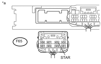
Text in Illustration *a Rear view of wire harness connector
(to Certification ECU (Smart Key ECU Assembly))
Disconnect the certification ECU (smart key ECU assembly) connector.
-
Depress the clutch pedal.
-
Measure the resistance according to the value(s) in the table below.
Standard Resistance Tester Connection Condition Specified Condition F65-5 (STAR) - Body ground 20°C (68°F) 93.75 to 136.36 Ω
OK
REPLACE CERTIFICATION ECU (SMART KEY ECU ASSEMBLY)
NG
REPAIR OR REPLACE HARNESS OR CONNECTOR
-
-
CHECK FOR DTC
-
Check the DTCs Click here.
Result Result Proceed to DTC is not output A DTC B2784 is output B DTC B2785 is output C
A
REPLACE ELECTRICAL KEY TRANSMITTER SUB-ASSEMBLY
B
GO TO DIAGNOSTIC TROUBLE CODE CHART (B2784) Click here
C
GO TO DIAGNOSTIC TROUBLE CODE CHART (B2785) Click here
-
-
READ VALUE USING INTELLIGENT TESTER (START SWITCH 1, 2)
-
Connect the intelligent tester to the DLC3.
-
Turn the engine switch on (IG).
-
Turn the intelligent tester on.
-
Enter the following menus: Body / Power Source Control / Data List.
-
According to the display on the intelligent tester, read the Data List.
Power Source Control Tester Display Measurement Item/Range Normal Condition Diagnostic Note Start Switch 1 Condition of engine switch contact 1 / OFF or ON OFF: Engine switch not pushed
ON: Engine switch pushed
-
If the engine switch is pressed for a short time, the display may not change.
-
Use this item to determine whether the engine switch input signal is malfunctioning.
Start Switch 2 Condition of engine switch contact 2 / OFF or ON OFF: Engine switch not pushed
ON : Engine switch pushed
-
Backup for engine switch 1. However, when the engine switch is pressed and held, the control functions only when both engine switch 1 and 2 are normal.
-
Behaves the same way as engine switch 1.
OK The ECU data monitor changes in response to the operation of the engine switch. Result Result Proceed to NG A OK B -
B
GO TO ENTRY AND START SYSTEM (FOR ENTRY FUNCTION) (ROOM OSCILLATOR DOES NOT RECOGNIZE KEY) Click here
A
-
-
INSPECT ENGINE SWITCH
-
Inspect the engine switch Click here.
Result Result Proceed to OK A NG (for 1KR-FE) B NG (for 1NR-FE) C NG (for 1ND-TV) D
B
REPLACE ENGINE SWITCH Click here
C
REPLACE ENGINE SWITCH Click here
D
REPLACE ENGINE SWITCH Click here
A
-
-
CHECK HARNESS AND CONNECTOR (CERTIFICATION ECU (SMART KEY ECU ASSEMBLY) - ENGINE SWITCH)
-
Disconnect the F63 certification ECU (smart key ECU assembly) connector.
-
Disconnect the F59 engine switch connector.
-
Measure the resistance according to the value(s) in the table below.
Standard Resistance Tester Connection Condition Specified Condition F63-28 (SSW1) - F59-5 (SS1) Always Below 1 Ω F63-30 (SSW2) - F59-1 (SS2) Always Below 1 Ω F63-28 (SSW1) or F59-5 (SS1) - Body ground Always 10 kΩ or higher F63-30 (SSW2) or F59-1 (SS2) - Body ground Always 10 kΩ or higher
OK
REPLACE CERTIFICATION ECU (SMART KEY ECU ASSEMBLY)
NG
REPAIR OR REPLACE HARNESS OR CONNECTOR
-