ENTRY AND START SYSTEM(for Start Function), Diagnostic DTC:B2286, P0335
| DTC Code | DTC Name |
|---|---|
| B2286 | Runnable Signal Malfunction |
| P0335 | Crankshaft Position Sensor "A" Circuit |
DESCRIPTION
These DTCs are stored when the engine speed signal sent by the ECM via direct line and the engine speed signal sent via CAN communication do not match.
Tech Tips
When the battery cable is disconnected and reconnected, the power source returns to the mode it was in before the battery cable was disconnected.
| DTC No. | DTC Detection Condition | Trouble Area | DTC Output Confirmation Operation |
|---|---|---|---|
| B2286 | The engine speed signal sent by the ECM via direct line and the engine speed signal sent via CAN communication (1- trip detection logic*) do not match. |
|
Disconnect the cable from the negative (-) battery terminal, wait 30 seconds and reconnect the cable to the negative (-) battery terminal. Wait 20 seconds or more with the engine switch off, and then start the engine. Make sure that the engine speed is 1000 rpm or more for 20 seconds or more after starting the engine. |
| P0335 | The engine speed signal sent by the ECM via direct line and the engine speed signal sent via CAN communication (1- trip detection logic*) do not match. |
|
Wait for 10 seconds or more with the engine idling. |
*: Only output while a malfunction is present and the engine switch is on (IG)
| Vehicle Condition when Malfunction Detected | Fail-safe Function when Malfunction Detected |
|---|---|
|
|
| DTC No. | Data List Item | Active Test Item |
|---|---|---|
| B2286 B228A P0335 |
Power Source Control
Starting Control |
- |
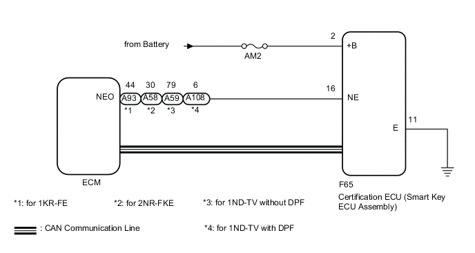
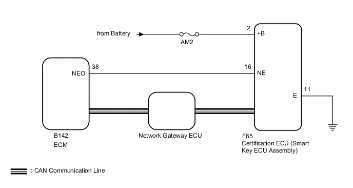
WIRING DIAGRAM
-
except GRMN
-
for GRMN
CAUTION / NOTICE / HINT
Note
-
When using the GTS with the engine switch off, connect the GTS to the DLC3 and turn a courtesy light switch on and off at intervals of 1.5 seconds or less until communication between the GTS and the vehicle begins. Then select Model Code "KEY REGIST" under manual mode and enter the following menus: Body Electrical / Entry&Start(CAN). While using the GTS, periodically turn a courtesy light switch on and off at intervals of 1.5 seconds or less to maintain communication between the GTS and the vehicle.
-
The entry and start system uses multiplex communication. First perform the inspections in "How to Proceed with Troubleshooting" to confirm that there are no communication malfunctions before proceeding with troubleshooting Click here.
-
Before replacing the certification ECU (smart key ECU assembly), refer to the entry and start system (for Entry Function) Click here.
-
After performing repairs, perform the operation that fulfills the DTC output confirmation operation, and then confirm that no DTCs are output again.
-
Inspect the fuses of circuits related to this system before performing the following inspection procedure.
PROCEDURE
-
CHECK VEHICLE TYPE
-
Check vehicle type.
Result Result Proceed to except GRMN A for GRMN B
B 
READ VALUE USING GTS (ENGINE CONDITION, ENGINE SPEED) Click here
A 
-
-
READ VALUE USING GTS (ENGINE CONDITION, ENGINE SPEED)
-
Connect the GTS to the DLC3.
-
Turn the engine switch on (IG).
-
Turn the GTS on.
-
Enter the following menus: Body Electrical / Power Source Control or Starting Control / Data List.
-
According to the display on the GTS, read the Data List.
Power Source Control Tester Display Measurement Item/Range Normal Condition Diagnostic Note Engine Condition Condition of engine / Stop or Run Stop: Engine is stopped
Run: Engine is running
- Starting Control Tester Display Measurement Item/Range Normal Condition Diagnostic Note Engine Speed Engine speed / 0 to 16383 r/min Changes according to engine speed - OK The Data List items change in accordance with the engine condition. Result Result Proceed to NG A OK (for 1KR-FE) B OK (for 2NR-FKE) C OK (for 1ND-TV with DPF) D OK (for 1ND-TV without DPF) E
B 
GO TO SFI SYSTEM (HOW TO PROCEEDWITH TROUBLESHOOTING) Click here
C
GO TO SFI SYSTEM (HOW TO PROCEEDWITH TROUBLESHOOTING) Click here
D
GO TO ECD SYSTEM (HOW TO PROCEEDWITH TROUBLESHOOTING) Click here
E
GO TO ECD SYSTEM (HOW TO PROCEEDWITH TROUBLESHOOTING) Click here
A
-
-
CHECK HARNESS AND CONNECTOR (POWER SOURCE)
NG
REPAIR OR REPLACE HARNESS OR CONNECTOR IN CIRCUIT CONNECTED TO POWER SOURCE
OK
-
CHECK HARNESS AND CONNECTOR (GROUND)
NG
REPAIR OR REPLACE HARNESS OR CONNECTOR
OK
-
CHECK HARNESS AND CONNECTOR (CERTIFICATION ECU (SMART KEY ECU ASSEMBLY) - ECM)
-
Disconnect the F65 certification ECU (smart key ECU assembly) connector.
-
Disconnect the A93*1, A58*2, A59*3 or A108*4 ECM connector.
-
*1: for 1KR-FE
-
*2: for 2NR-FKE
-
*3: for 1ND-TV without DPF
-
*4: for 1ND-TV with DPF
-
-
Measure the resistance according to the value(s) in the table below.
Standard Resistance for 1KR-FE Tester Connection Condition Specified Condition F65-16 (NE) - A93-44 (NEO) Always Below 1 Ω F65-16 (NE) or A93-44 (NEO) - Body ground Always 10 kΩ or higher for 2NR-FKE Tester Connection Condition Specified Condition F65-16 (NE) - A58-30 (NEO) Always Below 1 Ω F65-16 (NE) or A58-30 (NEO) - Body ground Always 10 kΩ or higher for 1ND-TV without DPF Tester Connection Condition Specified Condition F65-16 (NE) - A59-79 (NEO) Always Below 1 Ω F65-16 (NE) or A59-79 (NEO) - Body ground Always 10 kΩ or higher for 1ND-TV with DPF Tester Connection Condition Specified Condition F65-16 (NE) - A108-6 (NEO) Always Below 1 Ω F65-16 (NE) or A108-6 (NEO) - Body ground Always 10 kΩ or higher
NG
REPAIR OR REPLACE HARNESS OR CONNECTOR
OK
-
-
INSPECT CERTIFICATION ECU (SMART KEY ECU ASSEMBLY)
-
Reconnect the A93*1, A58*2, A59*3 or A108*4 ECM connector.
-
*1: for 1KR-FE
-
*2: for 2NR-FKE
-
*3: for 1ND-TV without DPF
-
*4: for 1ND-TV with DPF
-
-
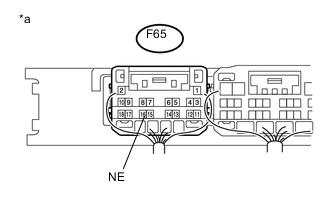
Text in Illustration *a Component with harness connected
(Certification ECU (Smart Key ECU Assembly))
Reconnect the F65 certification ECU (smart key ECU assembly) connector.
-
Check the signal waveform according to the condition(s) in the table below.
OK Tester Connection Condition Specified Condition F65-16 (NE) - Body ground Engine is stopped No pulse generated Engine is running Pulse generated Result Result Proceed to OK A NG (for 1KR-FE) B NG (for 2NR-FKE) C NG (for 1ND-TV with DPF) D NG (for 1ND-TV without DPF) E
A
REPLACE CERTIFICATION ECU (SMART KEY ECU ASSEMBLY)
B
GO TO SFI SYSTEM (HOW TO PROCEEDWITH TROUBLESHOOTING) Click here
C
GO TO SFI SYSTEM (HOW TO PROCEEDWITH TROUBLESHOOTING) Click here
D
GO TO ECD SYSTEM (HOW TO PROCEEDWITH TROUBLESHOOTING) Click here
E
GO TO ECD SYSTEM (HOW TO PROCEEDWITH TROUBLESHOOTING) Click here
-
-
READ VALUE USING GTS (ENGINE CONDITION, ENGINE SPEED)
-
Connect the GTS to the DLC3.
-
Turn the engine switch on (IG).
-
Turn the GTS on.
-
Enter the following menus: Body Electrical / Power Source Control or Starting Control / Data List.
-
According to the display on the GTS, read the Data List.
Power Source Control Tester Display Measurement Item/Range Normal Condition Diagnostic Note Engine Condition Condition of engine / Stop or Run Stop: Engine is stopped
Run: Engine is running
- Starting Control Tester Display Measurement Item/Range Normal Condition Diagnostic Note Engine Speed Engine speed / 0 to 16383 r/min Changes according to engine speed - OK The Data List items change in accordance with the engine condition. Result Result Proceed to NG A OK B
B
GO TO SFI SYSTEM Click here
A
-
-
CHECK HARNESS AND CONNECTOR (POWER SOURCE)
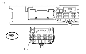
Text in Illustration *a Rear view of harness connected
(to Certification ECU (Smart Key ECU Assembly))
-
Disconnect the F65 certification ECU (smart key ECU assembly) connector.
-
Measure the voltage according to the value(s) in the table below.
Standard Voltage Tester Connection Condition Specified Condition F65-2 (+B) - Body ground Always 9.5 to 16 V
NG
REPAIR OR REPLACE HARNESS OR CONNECTOR IN CIRCUIT CONNECTED TO POWER SOURCE
OK
-
-
CHECK HARNESS AND CONNECTOR (GROUND)
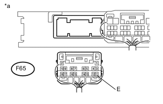
Text in Illustration *a Rear view of harness connected
(to Certification ECU (Smart Key ECU Assembly))
-
Disconnect the F65 certification ECU (smart key ECU assembly) connector.
-
Measure the resistance according to the value(s) in the table below.
Standard Resistance Tester Connection Condition Specified Condition F65-11 (E) - Body ground Always Below 1 Ω
NG
REPAIR OR REPLACE HARNESS OR CONNECTOR
OK
-
-
HARNESS AND CONNECTOR (CERTIFICATION ECU (SMART KEY ECU ASSEMBLY) - ECM)
-
Disconnect the F65 certification ECU (smart key ECU assembly) connector.
-
Disconnect the B142 ECM connector.
-
Measure the resistance according to the value(s) in the table below.
Standard Resistance Tester Connection Condition Specified Condition F65-16 (NE) - B142-38 (NEO) Always Below 1 Ω F65-16 (NE) or B142-38 (NEO) - Body ground Always 10 kΩ or higher
NG
REPAIR OR REPLACE HARNESS OR CONNECTOR
OK
-
-
INSPECT CERTIFICATION ECU (SMART KEY ECU ASSEMBLY)
-
Reconnect the B142 ECM connector.
-

Text in Illustration *a Component with harness connected
(Certification ECU (Smart Key ECU Assembly))
Reconnect the F65 certification ECU (smart key ECU assembly) connector.
-
Check the signal waveform according to the condition(s) in the table below.
OK Tester Connection Condition Specified Condition F65-16 (NE) - Body ground Engine is stopped No pulse generated Engine is running Pulse generated
OK
REPLACE CERTIFICATION ECU (SMART KEY ECU ASSEMBLY)
NG
GO TO SFI SYSTEM Click here
-