ENTRY AND START SYSTEM(for Entry Function) Front Passenger Side Door Entry Lock Function does not Operate
DESCRIPTION
If the front passenger side door entry lock function does not operate but the entry unlock function operates, the communication between the vehicle and electrical key transmitter sub-assembly is normal. The malfunctioning part may be the lock sensor circuit (from certification ECU (smart key ECU assembly) to the front door outside handle assembly (for front passenger side electrical key antenna)).
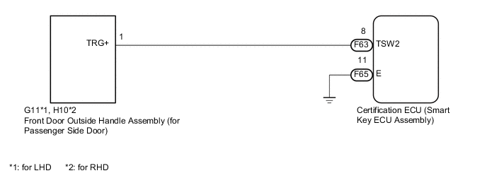
WIRING DIAGRAM
CAUTION / NOTICE / HINT
Note
-
When using the GTS with the engine switch off, connect the GTS to the DLC3 and turn a courtesy light switch on and off at intervals of 1.5 seconds or less until communication between the GTS and the vehicle begins. Then select Model Code "KEY REGIST" under manual mode and enter the following menus: Body Electrical / Entry&Start(CAN). While using the GTS, periodically turn a courtesy light switch on and off at intervals of 1.5 seconds or less to maintain communication between the GTS and the vehicle.
-
The entry and start system (for Entry Function) uses a LIN communication system and CAN communication system. Inspect the communication function by following How to Proceed with Troubleshooting Click here. Troubleshoot the entry and start system (for Entry Function) after confirming that the communication system is functioning properly.
-
Before replacing the certification ECU (smart key ECU assembly), refer to the entry and start system (for Entry Function) Click here.
-
Check that there are no electrical key transmitter sub-assemblies in the vehicle.
-
When checking the entry lock operation multiple times, the lock operation may be limited to 2 consecutive operations depending on the settings. In order to perform the entry lock operation 3 or more times, an unlock operation must be performed once (any type of unlock operation is sufficient). However, only consecutive entry lock operations are limited. Using the wireless lock or other types of lock operations, it is possible to perform consecutive lock operations without this limitation.
PROCEDURE
-
CHECK POWER DOOR LOCK OPERATION
-
When the door control switch on the master switch assembly is operated, check that the doors unlock and lock according to switch operation Click here.
OK Door locks operate normally.
NG 
GO TO POWER DOOR LOCK CONTROL SYSTEM (PROCEED TO PROBLEM SYMPTOMS TABLE) Click here
OK 
-
-
READ VALUE USING GTS (P-DOOR TRIGGER SWITCH)
-
Connect the GTS to the DLC3.
-
Turn the engine switch on (IG).
-
Turn the GTS on.
-
Enter the following menus: Body Electrical / Entry & Start / Data List.
-
Read the Data List according to the display on the GTS.
Entry & Start Tester Display Measurement Item/Range Normal Condition Diagnostic Note P-Door Trigger Switch Front door outside handle assembly (for front passenger side) (unlock sensor) / OFF or ON OFF: Front door outside handle assembly (for passenger side) (unlock sensor) not touched
ON: Front door outside handle assembly (for passenger side) (unlock sensor) touched
-
Displays whether the lock sensor is on or off (even if the sensor is touched and contact is maintained, "ON" is displayed only momentarily).
-
Use this Data List item to help determine if there is a lock sensor malfunction when the entry lock function does not operate.
OK On the GTS screen, the display changes between ON and OFF as shown in the table above. -
OK
REPLACE CERTIFICATION ECU (SMART KEY ECU ASSEMBLY)
NG
-
-
CHECK HARNESS AND CONNECTOR (CERTIFICATION ECU (SMART KEY ECU ASSEMBLY) - FRONT DOOR OUTSIDE HANDLE ASSEMBLY)
-
Disconnect the F63 certification ECU (smart key ECU assembly) connector.
-
Disconnect the G11*1 or H10*2 front door outside handle assembly (for passenger side door) connector.
-
*1: for LHD
-
*2: for RHD
-
-
Measure the resistance according to the value(s) in the table below.
Standard Resistance for LHD Tester Connection Condition Specified Condition F63-8 (TSW2) - G11-1 (TRG+) Always Below 1 Ω F65-11 (E) - Body ground Always Below 1 Ω F63-8 (TSW2) or G11-1 (TRG+) - Body ground Always 10 kΩ or higher for RHD Tester Connection Condition Specified Condition F63-8 (TSW2) - H10-1 (TRG+) Always Below 1 Ω F65-11 (E) - Body ground Always Below 1 Ω F63-8 (TSW2) or H10-1 (TRG+) - Body ground Always 10 kΩ or higher
NG
REPAIR OR REPLACE HARNESS OR CONNECTOR
OK
-
-
INSPECT FRONT DOOR OUTSIDE HANDLE ASSEMBLY (FOR PASSENGER SIDE DOOR)
-
Reconnect the F63 certification ECU (smart key ECU assembly) connector.
-
Reconnect the G11*1 or H10*2 front door outside handle assembly (for passenger side door) connector.
-
*1: for LHD
-
*2: for RHD
-
-
Measure the voltage according to the value(s) in the table below.
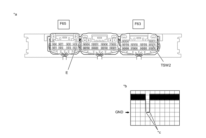
*a Component with harness connected
(Certification ECU (smart key ECU assembly))
*b Waveform *c In actuality, sampling is being performed - - OK Tester Connection Switch Condition Tool Setting Specified Condition F63-8 (TSW2) - F65-11 (E) Procedure:
-
Engine switch off
-
Electrical key transmitter sub-assembly brought outside vehicle
-
All doors closed
-
Electrical key transmitter sub-assembly brought outside detection area*1
-
Electrical key transmitter sub-assembly not sufficiently close to vehicle
-
Front passenger side door lock sensor not touched → touched
2 V/DIV., 500 ms/DIV. Pulse generation
(See waveform)
-
*1: For details about the areas that are outside the entry function detection area, refer to Operation Check Click here.
-
OK
REPLACE CERTIFICATION ECU (SMART KEY ECU ASSEMBLY)
NG
REPLACE FRONT DOOR OUTSIDE HANDLE ASSEMBLY (FOR PASSENGER SIDE DOOR) Click here
-