ENTRY AND START SYSTEM(for Entry Function) Wireless Door Lock Buzzer Does not Sound
DESCRIPTION
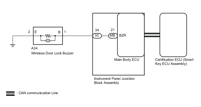
The entry and start system uses the wireless door lock buzzer to perform various vehicle exterior warnings. When the conditions for each warning are met, the certification ECU (smart key ECU assembly) sends a buzzer signal to the main body ECU via CAN communication, the main body ECU sends the signal to the wireless door lock buzzer, and the wireless door lock buzzer sounds.
WIRING DIAGRAM
CAUTION / NOTICE / HINT
Note
-
When using the GTS with the engine switch off, connect the GTS to the DLC3 and turn a courtesy light switch on and off at intervals of 1.5 seconds or less until communication between the GTS and the vehicle begins. Then select Model Code "KEY REGIST" under manual mode and enter the following menus: Body Electrical / Entry&Start(CAN). While using the GTS, periodically turn a courtesy light switch on and off at intervals of 1.5 seconds or less to maintain communication between the GTS and the vehicle.
-
The entry and start system (for Entry Function) uses a LIN communication system and CAN communication system. Inspect the communication function by following How to Proceed with Troubleshooting Click here. Troubleshoot the entry and start system (for Entry Function) after confirming that the communication system is functioning properly.
-
Before replacing the certification ECU (smart key ECU assembly), refer to the entry and start system (for Entry Function) Click here.
PROCEDURE
-
PERFORM ACTIVE TEST USING GTS (WIRELESS BUZZER)
-
Connect the GTS to the DLC3.
-
Turn the engine switch on (IG).
-
Turn the GTS on.
-
Enter the following menus: Body Electrical / Main Body Electrical / Active Test.
-
According to the display on the GTS, perform the Active Test.
Main Body Tester Display Test Part Control Range Diagnostic Note Wireless Buzzer Wireless door lock buzzer OFF/ON - OK Wireless door lock buzzer sounds.
OK 
REPLACE CERTIFICATION ECU (SMART KEY ECU ASSEMBLY)
NG 
-
-
INSPECT WIRELESS DOOR LOCK BUZZER
-
Inspect the wireless door lock buzzer Click here.
NG
REPLACE WIRELESS DOOR LOCK BUZZER Click here
OK
-
-
CHECK HARNESS AND CONNECTOR (INSTRUMENT PANEL JUNCTION BLOCK ASSEMBLY - WIRELESS DOOR LOCK BUZZER AND BODY GROUND)
-
Disconnect the A34 wireless door lock buzzer connector.
-
Disconnect the 3C instrument panel junction block assembly connector.
-
Measure the resistance according to the value(s) in the table below.
Standard Resistance Tester Connection Condition Specified Condition 3C-34 - A34-1(B) Always Below 1 Ω A34-2 (E) - Body ground Always Below 1 Ω 3C-34 - Body ground Always 10 kΩ or higher
NG
REPAIR OR REPLACE HARNESS OR CONNECTOR
OK
-
-
REPLACE MAIN BODY ECU
-
Temporarily replace the main body ECU with a new or normally functioning one Click here.
NEXT
-
-
PERFORM ACTIVE TEST USING GTS (WIRELESS BUZZER)
-
Connect the GTS to the DLC3.
-
Turn the engine switch on (IG).
-
Turn the GTS on.
-
Enter the following menus: Body Electrical / Main Body Electrical / Active Test.
-
According to the display on the GTS, perform the Active Test.
Main Body Tester Display Test Part Control Range Diagnostic Note Wireless Buzzer Wireless door lock buzzer OFF/ON - OK Wireless buzzer turns ON/OFF.
OK
REPLACE CERTIFICATION ECU (SMART KEY ECU ASSEMBLY)
NG
REPLACE INSTRUMENT PANEL JUNCTION BLOCK ASSEMBLY Click here
-