WIRELESS DOOR LOCK CONTROL SYSTEM(w/o Entry and Start System) TERMINALS OF ECU
-
CHECK MAIN BODY ECU AND INSTRUMENT PANEL JUNCTION BLOCK ASSEMBLY
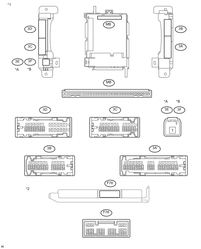
Text in Illustration *A for LHD *B for RHD *1 Instrument Panel Junction Block Assembly *2 Main Body ECU
-
Remove the main body ECU from the instrument panel junction block assembly.
-
Measure the resistance and voltage between each terminal of the wire harness side connectors and body ground.
Terminal No. (Symbol) Wiring Color Terminal Description Condition Specified Condition MB-11 (GND1) - Body ground None - Body ground Ground Always Below 1 Ω MB-30 (BECU) - Body ground None - Body ground Battery power supply Always 11 to 14 V MB-32 (IG) - Body ground None - Body ground Ignition switch power supply Ignition switch ON 11 to 14 V Ignition switch off Below 1 V MB-29 (ACC) - Body ground None - Body ground ACC power supply Ignition switch ACC 11 to 14 V Ignition switch off Below 1 V -
Install the main body ECU to the instrument panel junction block assembly.
-
Measure the voltage and resistance, check for pulse according to the valve(s) in the table below.
Terminal No. (Symbol) Wiring Color Terminal Description Condition Specified Condition 3D-36 (FLCY) - Body ground L - Body ground Front door LH courtesy light switch input Front door LH open Below 1 V Front door LH closed Pulse generation F76-19 (FRCY) - Body ground Y - Body ground Front door RH courtesy light switch input Front door RH open Below 1 V Front door RH closed Pulse generation F76-6 (LRCY) - Body ground*1 G - Body ground Rear door courtesy light switch input Rear door LH or RH open Below 1 V Rear door LH and RH closed Pulse generation 3D-35 (BCTY) - Body ground B - Body ground Back door courtesy light switch input Back door open Below 1 V Back door closed 11 to 14 V F76-17 (KSW) - Body ground Y - Body ground Unlock warning switch input No key in ignition key cylinder (off) Pulse generation Key inserted (on) Below 1 V 3B-2 (ACT+) - Body ground V - Body ground Door lock motor lock drive output (for front RH side) Driver side door control switch not pushed and driver side door key cylinder in neutral position Below 1 V Lock side of driver side door control switch pushed or driver side door key cylinder in lock position 11 to 14 V 3B-1 (ACT+) - Body ground Y - Body ground Door lock motor lock drive output (for front LH side) Driver side door control switch not pushed and driver side door key cylinder in neutral position Below 1 V Lock side of driver side door control switch pushed or driver side door key cylinder in lock position 11 to 14 V 3D-12 (ACT+) - Body ground*1 L - Body ground Door lock motor lock drive output (for rear RH side) Driver side door control switch not pushed and driver side door key cylinder in neutral position Below 1 V Lock side of driver side door control switch pushed or driver side door key cylinder in lock position 11 to 14 V 3D-11 (ACT+) - Body ground*1 GR - Body ground Door lock motor lock drive output (for rear LH side) Driver side door control switch not pushed and driver side door key cylinder in neutral position Below 1 V Lock side of driver side door control switch pushed or driver side door key cylinder in lock position 11 to 14 V 3B-3 (ACT-) - Body ground R - Body ground Door lock motor unlock drive output (for front RH side) Driver side door control switch not pushed and driver side door key cylinder in neutral position Below 1 V Unlock side of - driver side door control switch pushed or driver side door key cylinder in unlock position 11 to 14 V 3B-4 (ACT-) - Body ground L - Body ground Door lock motor unlock drive output (for front LH side) Driver side door control switch not pushed and driver side door key cylinder in neutral position Below 1 V Unlock side of - driver side door control switch pushed or driver side door key cylinder in unlock position 11 to 14 V 3D-8 (ACT-) - Body ground*1 P - Body ground Door lock motor unlock drive output (for rear RH side) Driver side door control switch not pushed and driver side door key cylinder in neutral position Below 1 V Unlock side of - driver side door control switch pushed or driver side door key cylinder in unlock position 11 to 14 V 3D-7 (ACT-) - Body ground*1 LG - Body ground Door lock motor unlock drive output (for rear LH side) Driver side door control switch not pushed and driver side door key cylinder in neutral position Below 1 V Unlock side of - driver side door control switch pushed or driver side door key cylinder in unlock position 11 to 14 V F76-18 (LSFR) - Body ground LG - Body ground*3 Front door RH unlock detection switch input Front door RH unlocked Below 1 V LG - Body ground*4, *5 Front door RH locked Pulse generation R - Body ground*4, *6 F76-7 (LSFL) - Body ground L - Body ground*3, *5 Front door LH unlock detection switch input Front door LH unlocked Below 1 V L - Body ground*4 R - Body ground*3, *6 Front door LH locked Pulse generation 3D-25 (LSR) - Body ground*1, *2 V - Body ground Rear door RH unlock detection switch input Rear door RH or LH unlocked Below 1 V Rear door RH and LH locked Pulse generation 3D-24 (LSR) - Body ground*1, *2 Y - Body ground Rear door LH unlock detection switch input Rear door LH or RH unlocked Below 1 V Rear door LH and RH locked Below 1 V F76-25 (PRG) - Body ground GR - Body ground Signal output to door control receiver Key inserted into ignition key cylinder → Key pulled out of ignition key cylinder 11 to 14 V → Pulse generation → 11 to 14 V F76-26 (RDA) - Body ground P - Body ground Signal input from door control receiver Ignition switch off, all doors closed and door control transmitter assembly switch not pressed 11 to 14 V Ignition switch off, all doors closed and door control transmitter assembly switch pressed Pulse generation
(0 to 12 V)
-
*1: for 5 Door
-
*2: w/ Double Locking System
-
*3: for LHD
-
*4: for RHD
-
*5: w/o Retract Mirror
-
*6: w/ Retract Mirror
-
-
-
CHECK DOOR CONTROL RECEIVER
-
Disconnect the K12 door control receiver connector.

-
Measure the voltage and resistance according to the value(s) in the table below.
Tech Tips
Measure the values on the wire harness side with the connectors disconnected.
Tester Connection Wiring Color Terminal Description Condition Specified Condition K12-5 (+B) - Body ground R - Body ground Battery power supply Always 11 to 14 V K12-1 (E) - Body ground W-B - Body ground Ground Always Below 1 Ω -
Reconnect the K12 door control receiver connector.
-
Measure the voltage according to the value(s) in the table below.
Terminal No. (Symbol) Wiring Color Terminal Description Condition Specified Condition K12-3 (PRG) - K12-1 (E) W - W-B*1
BE - W-B*2
Signal input from main body ECU
(multiplex network body ECU)
Key inserted into ignition key cylinder → Key pulled out of ignition key cylinder 11 to 14 V → Pulse generation → 11 to 14 V K12-2 (RDA) - K12-1 (E) Y - W-B Signal output to main body ECU
(multiplex network body ECU)
Ignition switch off, all doors closed and door control transmitter assembly switch not pressed 11 to 14 V Ignition switch off, all doors closed and door control transmitter assembly switch pressed Pulse generation
(0 to 12 V)
-
*1: w/o Tire Pressure Warning System
-
*2: w/ Tire Pressure Warning System
-
-