WIRELESS DOOR LOCK CONTROL SYSTEM(w/ Entry and Start System), Diagnostic DTC:B1242
| DTC Code | DTC Name |
|---|---|
| B1242 | Wireless Door Lock Tuner Circuit Malfunction |
DESCRIPTION
The door control receiver is used to receive electrical waves relating to the entry functions of the entry and start system. The certification ECU (smart key ECU assembly) decodes the requested entry and start system operation by identifying a key code based on the electric waves received via the door control receiver. The door control receiver receives a signal from the electrical key transmitter sub-assembly and sends signals to the main body ECU through the certification ECU (smart key ECU assembly). The certification ECU (smart key ECU assembly) then sends a command, according to the requested operation, to each ECU (ex. if door lock operation is requested, the certification ECU (smart key ECU assembly) sends a door lock command to the main body ECU).
| DTC No. | DTC Detection Condition | Trouble Area |
|---|---|---|
| B1242 |
|
|
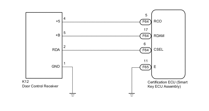
WIRING DIAGRAM
CAUTION / NOTICE / HINT
Note
-
When using the intelligent tester with the engine switch off, perform either of the following: 1) Turn a courtesy light switch on and off at intervals of 1.5 seconds or less until communication between the intelligent tester and vehicle begins, or 2) connect the intelligent tester to the vehicle and select "Manual" from the initial screen on the intelligent tester. Select "KEY REGIST" under Model Code.
-
The wireless door lock control system uses multiplex communication. First perform the inspections in "How to Proceed with Troubleshooting" to confirm that there are no communication malfunctions before proceeding with troubleshooting Click here.
-
Before replacing the certification ECU (smart key ECU assembly), refer to the entry and start system (for Entry Function) Click here.
-
When replacing or inspecting the door control receiver and wire harness, do not change the position or length of the wire harness. If the wire harness is too close to the door control receiver, entry and wireless function performance may be affected.
PROCEDURE
-
INSPECT CERTIFICATION ECU (SMART KEY ECU ASSEMBLY)
-
Disconnect the K12 door control receiver connector.
-
Measure the resistance and voltage according to the value(s) in the table below.
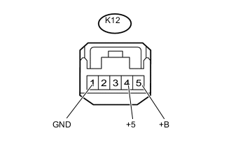
Standard Resistance Tester Connection Condition Specified Condition K12-1 (GND) - Body ground Always Below 1 Ω Standard Voltage Tester Connection Condition Specified Condition K12-4 (+5) - K12-1 (GND) Always Below 1 V →4.5 to 5.5 V
(Pulse generation)
K12-5 (+B) - K12-1 (GND) Always 11 to 14 V Text in Illustration *1 Front view of wire harness connector
(to Door Control Receiver)
NG 
REPLACE DOOR CONTROL RECEIVER Click here
OK 
-
-
CHECK HARNESS AND CONNECTOR (DOOR CONTROL RECEIVER - CERTIFICATION ECU (SMART KEY ECU))
-
Disconnect the F64 and F65 certification ECU (smart key ECU assembly) connectors.
-
Disconnect the K12 door control receiver connector.
-
Measure the resistance according to the value(s) in the table below.
Standard Resistance Tester Connection Condition Specified Condition F64-6 (CSEL) - K12-2 (RDA) Always Below 1 Ω F64-17 (RDAM) - K12-5 (+B) Always Below 1 Ω F64-5 (RCO) - K12-4 (+5) Always Below 1 Ω F65-11 (E) - Body ground Always Below 1 Ω K12-1 (GND) - Body ground Always Below 1 Ω F64-5 (RCO) - Body ground Always 10 kΩ or higher F64-17 (RDAM) - Body ground Always 10 kΩ or higher F64-6 (CSEL) - Body ground Always 10 kΩ or higher
OK
REPLACE CERTIFICATION ECU (SMART KEY ECU ASSEMBLY)
NG
REPAIR OR REPLACE HARNESS OR CONNECTOR
-