POWER DOOR LOCK CONTROL SYSTEM All Doors LOCK / UNLOCK Functions do not Operate Via Master Switch, Both Front Door Key Cylinders
DESCRIPTION
The main body ECU receives switch signals from the door control switch, and driver side door key cylinder switch, activates the door lock motor on each door accordingly.
WIRING DIAGRAM
PROCEDURE
-
CHECK DOOR LOCK OPERATION
-
Proceed to the next step according to the symptom listed in the table below.
Result Result Proceed to Doors cannot be locked through master switch A Doors cannot be locked through driver side door key cylinder B
B 
READ VALUE USING INTELLIGENT TESTER (DOOR LOCK AND UNLOCK SWITCH) Click here
A 
-
-
READ VALUE USING INTELLIGENT TESTER (DOOR LOCK SW-LOCK AND DOOR LOCK SW-UNLOCK)
-
Connect the intelligent tester to the DLC3.
-
Turn the ignition switch to ON.
-
Turn the intelligent tester on.
-
Enter the following menus: Body / Main Body / Data List.
-
According to the display on the intelligent tester, read the Data List.
Main Body Tester Display Measurement Item/Range Normal Condition Diagnostic Note Door Lock SW-Lock Door manual lock switch signal / OFF or ON OFF: Door control switch (for front driver door side) is turned to unlock position
ON: Door control switch (for front driver door side) is turned to lock position
- Door Lock SW-Unlock Door manual unlock switch signal / OFF or ON OFF: Door control switch (for front driver door side) is turned to lock position
ON: Door control switch (for front driver door side) is turned to unlock position
- OK When the switch is operating, the intelligent tester should display as shown in the table.
OK 
REPLACE MAIN BODY ECU Click here
NG
-
-
INSPECT POWER WINDOW REGULATOR MASTER SWITCH ASSEMBLY
-
Inspect the power window regulator master switch assembly Click here.
NG
REPLACE POWER WINDOW REGULATOR MASTER SWITCH ASSEMBLY Click here
OK
-
-
CHECK HARNESS AND CONNECTOR (POWER WINDOW REGULATOR MASTER SWITCH ASSEMBLY - MAIN BODY ECU AND BODY GROUND)
-
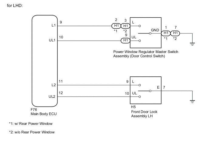
for LHD:
-
Disconnect the F76 main body ECU connector.
-
Disconnect the H1 power window regulator master switch assembly (door control switch) connector.
-
Measure the resistance according to the value(s) in the table below.
Standard Resistance w/ Rear Power Window Tester Connection Condition Specified Condition H1-2 (L) - F76-9 (L1) Always Below 1 Ω H1-9 (UL) - F76-10 (UL1) Always Below 1 Ω H1-1 (GND) - Body ground Always Below 1 Ω H1-2 (L) or F76-9 (L1) - Body ground Always 10 kΩ or higher H1-9 (UL) or F76-10 (UL1) - Body ground Always 10 kΩ or higher w/o Rear Power Window Tester Connection Condition Specified Condition H1-3 (L) - F76-9 (L1) Always Below 1 Ω H1-9 (UL) - F76-10 (UL1) Always Below 1 Ω H1-7 (GND) - Body ground Always Below 1 Ω H1-3 (L) or F76-9 (L1) - Body ground Always 10 kΩ or higher H1-9 (UL) or F76-10 (UL1) - Body ground Always 10 kΩ or higher
-
-
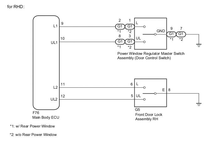
for RHD:
-
Disconnect the F76 main body ECU connector.
-
Disconnect the G1 power window regulator master switch assembly (door control switch) connector.
-
Measure the resistance according to the value(s) in the table below.
Standard Resistance w/ Rear Power Window Tester Connection Condition Specified Condition G1-2 (L) - F76-9 (L1) Always Below 1 Ω G1-8 (UL) - F76-10 (UL1) Always Below 1 Ω G1-9 (GND) - Body ground Always Below 1 Ω G1-2 (L) or F76-9 (L1) - Body ground Always 10 kΩ or higher G1-8 (UL) or F76-10 (UL1) - Body ground Always 10 kΩ or higher w/o Rear Power Window Tester Connection Condition Specified Condition G1-1 (L) - F76-9 (L1) Always Below 1 Ω G1-3 (UL) - F76-10 (UL1) Always Below 1 Ω G1-7 (GND) - Body ground Always Below 1 Ω G1-1 (L) or F76-9 (L1) - Body ground Always 10 kΩ or higher G1-3 (UL) - F76-10 (UL1) Always 10 kΩ or higher
-
OK
REPLACE MAIN BODY ECU Click here
NG
REPAIR OR REPLACE HARNESS OR CONNECTOR
-
-
READ VALUE USING INTELLIGENT TESTER (DOOR LOCK AND UNLOCK SWITCH)
-
Connect the intelligent tester to the DLC3.
-
Turn the ignition switch to ON.
-
Turn the intelligent tester on.
-
Enter the following menus: Body / Main Body / Data List.
-
According to the display on the intelligent tester, read the Data List.
Main Body Tester Display Measurement Item/Range Normal Condition Diagnostic Note Door Key SW-Lock Door lock and unlock switch signal / OFF or ON OFF: Driver side door key cylinder not turned
ON: Driver side door key cylinder turned to lock position
- Door Key SW-Unlock Door lock and unlock switch signal / OFF or ON OFF: Driver side door key cylinder not turned
ON: Driver side door key cylinder turned to unlock position
- OK ON (driver side door key cylinder is turned to lock /unlock position) appears on the tester screen.
OK
REPLACE MAIN BODY ECU Click here
NG
-
-
INSPECT FRONT DOOR LOCK ASSEMBLY (FOR DRIVER SIDE DOOR)
-
Inspect the front door lock assembly Click here.
NG
REPLACE FRONT DOOR LOCK ASSEMBLY Click here
OK
-
-
CHECK HARNESS AND CONNECTOR (MAIN BODY ECU - FRONT DOOR LOCK ASSEMBLY AND BODY GROUND)
-
for LHD:
-
Disconnect the F76 main body ECU.
-
Disconnect the H5 front door lock assembly LH connector.
-
Measure the resistance according to the value(s) in the table below.
Standard Resistance Tester Connection Condition Specified Condition H5-9 (L) - F76-11 (L2) Always Below 1 Ω H5-10 (UL) - F76-12 (UL2) Always Below 1 Ω H5-7 (E) - Body ground Always Below 1 Ω H5-9 (L) or F76-11 (L2) - Body ground Always 10 kΩ or higher H5-10 (UL) or F76-12 (UL2) - Body ground Always 10 kΩ or higher
-
-
for RHD:
-
Disconnect the F76 main body ECU.
-
Disconnect the G5 front door lock assembly RH connector.
-
Measure the resistance according to the value(s) in the table below.
Standard Resistance Tester Connection Condition Specified Condition G5-6 (L) - F76-11 (L2) Always Below 1 Ω G5-5 (UL) - F76-12 (UL2) Always Below 1 Ω G5-8 (E) - Body ground Always Below 1 Ω G5-6 (L) or F76-11 (L2) - Body ground Always 10 kΩ or higher G5-5 (UL) or F76-12 (UL2) - Body ground Always 10 kΩ or higher
-
OK
REPLACE MAIN BODY ECU Click here
NG
REPAIR OR REPLACE HARNESS OR CONNECTOR
-