CAN COMMUNICATION SYSTEM(w/o Toyota Safety Sense) Open in One Side of CAN Branch Line
DESCRIPTION
If 2 or more ECUs and/or sensors do not appear on the GTS "Bus Check" screen, one side of the CAN branch wire may be open (one side of the CANH [branch wire]/CANL [branch wire] of the ECU and/or sensor is open).
| Symptom | Trouble Area |
|---|---|
| 2 or more ECUs and/or sensors do not appear on the GTS "CAN Bus Check" screen. |
|
-
*1: w/ Entry and Start System
-
*2: w/ VSC
-
*3: w/ Display
-
*4: w/ Air Conditioning System or PTC Heater
-
*5: w/ Stop and Start System
-
*6: for GRMN
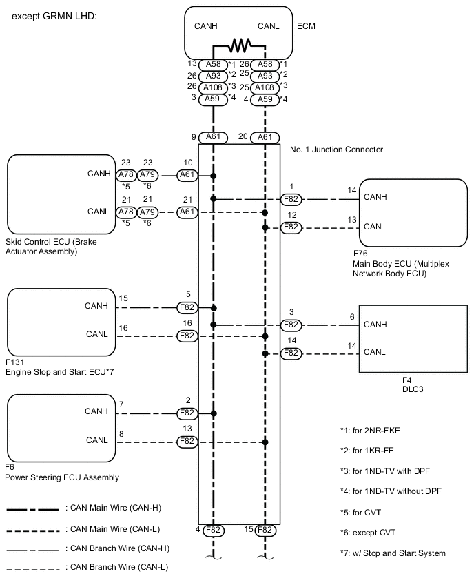
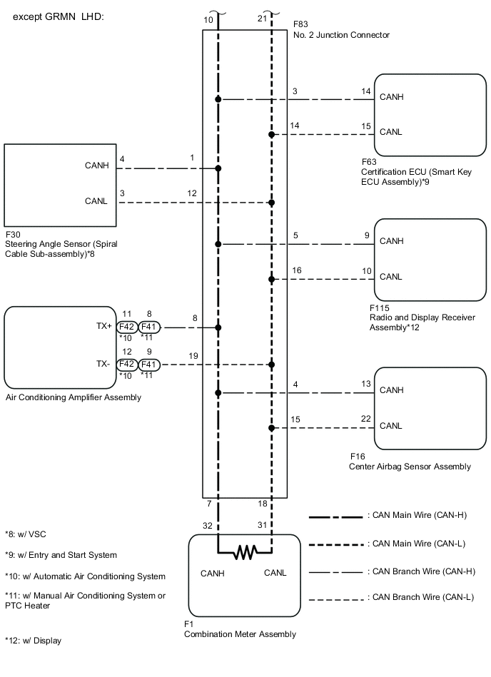
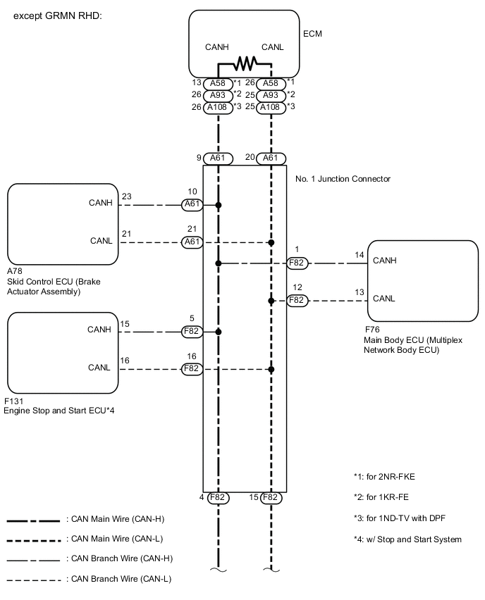
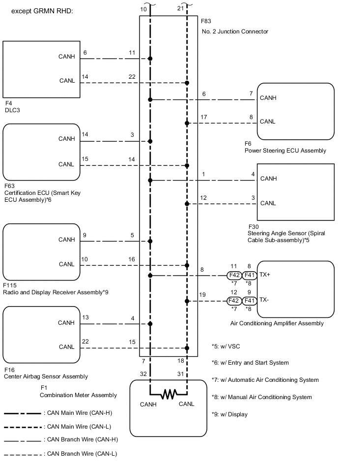
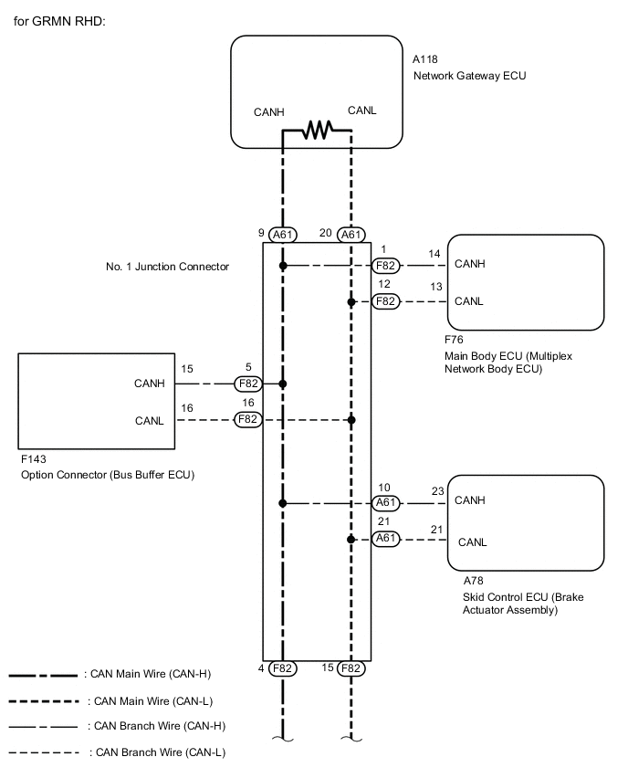
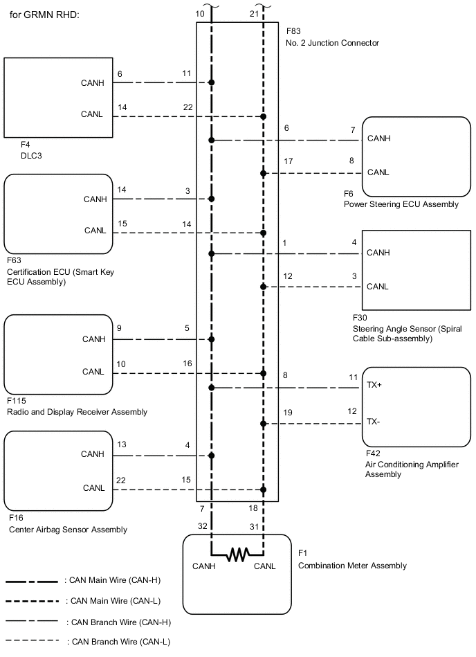
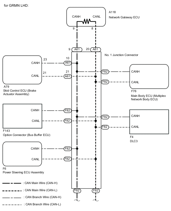
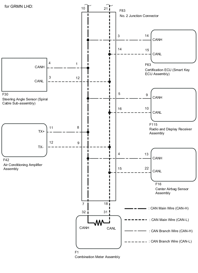
WIRING DIAGRAM
CAUTION / NOTICE / HINT
Note
-
Turn the ignition switch off before measuring the resistances of the CAN main wire and the CAN branch wire.
-
After the ignition switch is turned off, check that the key reminder warning system and light reminder warning system are not in operation.
-
Before measuring the resistance, leave the vehicle as is for at least 1 minute and do not operate the ignition switch, any other switches or the doors. If doors need to be opened in order to check connectors, open the doors and leave them open.
Tech Tips
-
Operating the ignition switch, any switches or any doors triggers related ECU and sensor communication with the CAN, which causes resistance variation.
-
Perform the following inspection for the ECUs (sensors) which are not displayed on the GTS. If a malfunction cannot be identified, perform the following inspections for the ECUs (sensors) connected to the CAN communication system.
-
Do not remove the combination meter assembly and ECM, as they are the end parts of the circuit. If removed, CAN communication will not be possible.
-
The open circuit confirmation of the combination meter assembly, ECM and main wire is performed in the "Check CAN Bus Line" procedure of "How to Proceed with Troubleshooting". This inspection only has procedures for checking for an open circuit on one side of the CAN branch wire.
PROCEDURE
-
CHECK OPEN IN ONE SIDE OF CAN BRANCH WIRE (SKID CONTROL ECU (BRAKE ACTUATOR ASSEMBLY))
-
Disconnect the A78*1 or A79*2 skid control ECU (brake actuator assembly) connector.
-
*1: for LHD with CVT and RHD
-
*2: for LHD with Manual Transaxle
-
-
Select "Communication Bus Check" from the screen on the GTS. Click here.
Result Result Proceed to "Skid Control (ABS/VSC/TRC)" not displayed on the GTS. A Several ECUs and sensors other than "Skid Control (ABS/VSC/TRC)" not displayed on the GTS. B
B 
CHECK OPEN IN ONE SIDE OF CAN BRANCH WIRE (RADIO AND DISPLAY RECEIVER ASSEMBLY) Click here
A 
-
-
CHECK OPEN IN ONE SIDE OF CAN BRANCH WIRE (SKID CONTROL ECU (BRAKE ACTUATOR ASSEMBLY) BRANCH WIRE)
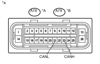
*A for LHD with CVT and RHD *B for LHD with Manual Transaxle *a Front view of wire harness connector
(to Skid Control ECU (Brake Actuator Assembly))
-
Measure the resistance according to the value(s) in the table below.
Standard Resistance Tester Connection Switch Condition Specified Condition A78-23 (CANH) - A78-21 (CANL)*1
A79-23 (CANH) - A79-21 (CANL)*2
Ignition switch off 54 to 69 Ω
-
*1: for LHD with CVT and RHD
-
*2: for LHD with Manual Transaxle
Result Result Proceed to NG A OK (for LHD) B OK (for RHD) C -
-
Reconnect the A78*1 or A79*2 skid control ECU (brake actuator assembly) connector.
-
*1: for LHD with CVT and RHD
-
*2: for LHD with Manual Transaxle
-
A 
REPAIR OR REPLACE CAN BUS BRANCH WIRE OR CONNECTOR (SKID CONTROL ECU (BRAKE ACTUATOR ASSEMBLY) BRANCH WIRE)
B
REPLACE SKID CONTROL ECU (BRAKE ACTUATOR ASSEMBLY) Click here
C
REPLACE SKID CONTROL ECU (BRAKE ACTUATOR ASSEMBLY) Click here
-
-
CHECK OPEN IN ONE SIDE OF CAN BRANCH WIRE (RADIO AND DISPLAY RECEIVER ASSEMBLY)
Tech Tips
For vehicles without display, go to step 5.
-
Disconnect the F115 radio and display receiver assembly connector.
-
Select "Communication Bus Check" on the GTS Click here.
Result Result Proceed to "Display and Navigation (AVN1)" not displayed on the GTS. A Several ECUs and sensors other than "Display and Navigation (AVN1)" not displayed on the GTS. B
B
CHECK OPEN IN ONE SIDE OF CAN BRANCH WIRE (AIR CONDITIONING AMPLIFIER ASSEMBLY) Click here
A
-
-
CHECK OPEN IN ONE SIDE OF CAN BRANCH WIRE (RADIO AND DISPLAY RECEIVER ASSEMBLY BRANCH WIRE)
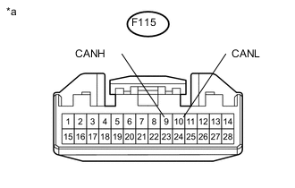
*a Front view of wire harness connector
(to Radio and Display Receiver Assembly)
-
Measure the resistance according to the value(s) in the table below.
Standard Resistance Tester Connection Switch Condition Specified Condition F115-9 (CANH) - F115-10 (CANL) Ignition switch off 54 to 69 Ω -
Reconnect the F115 radio and display receiver assembly connector.
OK
REPLACE RADIO AND DISPLAY RECEIVER ASSEMBLY Click here
NG
REPAIR OR REPLACE CAN BUS BRANCH WIRE OR CONNECTOR (RADIO AND DISPLAY RECEIVER ASSEMBLY BRANCH WIRE)
-
-
CHECK OPEN IN ONE SIDE OF CAN BRANCH WIRE (AIR CONDITIONING AMPLIFIER ASSEMBLY)
Tech Tips
For vehicles without air conditioning system or electrical type power heater system less, go to step 7.
-
Disconnect the F42*1 or F41*2 air conditioning amplifier assembly connector.
-
*1 : w/ Automatic Air Conditioning System
-
*2 : w/ Manual Air Conditioning System or PTC Heater
-
-
Select "Communication Bus Check" on the GTS Click here.
Result Result Proceed to "Air Conditioning Amplifier" not displayed on the GTS. A Several ECUs and sensors other than "Air Conditioning Amplifier" not displayed on the GTS. B
B
CHECK OPEN IN ONE SIDE OF CAN BRANCH WIRE (CENTER AIRBAG SENSOR ASSEMBLY) Click here
A
-
-
CHECK OPEN IN ONE SIDE OF CAN BRANCH WIRE (AIR CONDITIONING AMPLIFIER ASSEMBLY BRANCH WIRE)
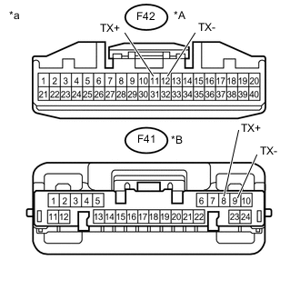
*A w/ Automatic Air Conditioning System *B w/ Manual Air Conditioning System or PTC Heater *a Front view of wire harness connector
(to Air Conditioning Amplifier Assembly)
-
Measure the resistance according to the value(s) in the table below.
Standard Resistance Tester Connection Switch Condition Specified Condition F42-11 (TX+) - F42-12 (TX-)*1
F41-8 (TX+) - F41-9 (TX-)*2
Ignition switch off 54 to 69 Ω
-
*1 : w/ Automatic Air Conditioning System
-
*2 : w/ Manual Air Conditioning System or PTC Heater
-
-
Reconnect the F42*1 or F41*2 air conditioning amplifier assembly connector.
-
*1 : w/ Automatic Air Conditioning System
-
*2 : w/ Manual Air Conditioning System or PTC Heater
-
OK
REPLACE AIR CONDITIONING AMPLIFIER ASSEMBLY Click here
NG
REPAIR OR REPLACE CAN BUS BRANCH WIRE OR CONNECTOR (AIR CONDITIONING AMPLIFIER ASSEMBLY BRANCH WIRE)
-
-
CHECK OPEN IN ONE SIDE OF CAN BRANCH WIRE (CENTER AIRBAG SENSOR ASSEMBLY)
-
Disconnect the F16 center airbag sensor assembly connector.
-
Select "Communication Bus Check" on the GTS Click here.
Result Result Proceed to "Airbag" not displayed on the GTS. A Several ECUs and sensors other than "Airbag" not displayed on the GTS. B
B
CHECK OPEN IN ONE SIDE OF CAN BRANCH WIRE (STEERING ANGLE SENSOR (SPIRAL CABLE SUB-ASSEMBLY)) Click here
A
-
-
CHECK OPEN IN ONE SIDE OF CAN BRANCH WIRE (CENTER AIRBAG SENSOR ASSEMBLY BRANCH WIRE)
-
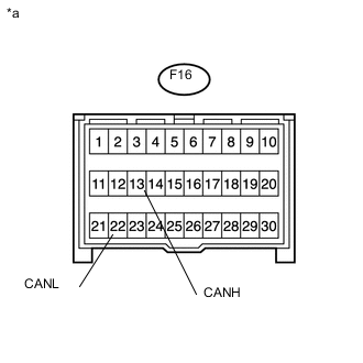
*a Front view of wire harness connector
(to Center Airbag sensor Assembly)
Measure the resistance according to the value(s) in the table below.
Standard Resistance Tester Connection Switch Condition Specified Condition F16-13 (CANH) - F16-22 (CANL) Ignition switch off 54 to 69 Ω -
Reconnect the F16 center airbag sensor assembly connector.
OK
REPLACE CENTER AIRBAG SENSOR ASSEMBLY Click here
NG
REPAIR OR REPLACE CAN BUS BRANCH WIRE OR CONNECTOR (CENTER AIRBAG SENSOR ASSEMBLY BRANCH WIRE)
-
-
CHECK OPEN IN ONE SIDE OF CAN BRANCH WIRE (STEERING ANGLE SENSOR (SPIRAL CABLE SUB-ASSEMBLY))
Tech Tips
For vehicles without VSC, go to step 11.
-
Disconnect the F30 steering angle sensor (spiral cable sub-assembly) connector.
-
Select "Communication Bus Check" on the GTS Click here.
Result Result Proceed to "Spiral cable (Steering Angle Sensor)" not displayed on the GTS. A Several ECUs and sensors other than "Spiral cable (Steering Angle Sensor)" not displayed on the GTS. B
B
CHECK OPEN IN ONE SIDE OF CAN BRANCH WIRE (MAIN BODY ECU (MULTIPLEX NETWORK BODY ECU)) Click here
A
-
-
CHECK OPEN IN ONE SIDE OF CAN BRANCH WIRE (STEERING ANGLE SENSOR (SPIRAL CABLE SUB-ASSEMBLY) BRANCH WIRE)
-
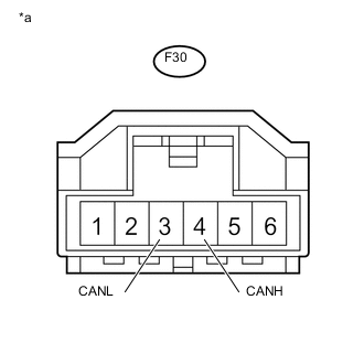
*a Front view of wire harness connector
(to Steering Angle Sensor (Spiral Cable Sub-assembly))
Measure the resistance according to the value(s) in the table below.
Standard Resistance Tester Connection Switch Condition Specified Condition F30-4 (CANH) - F30-3 (CANL) Ignition switch off 54 to 69 Ω -
Reconnect the F30 steering angle sensor (spiral cable sub-assembly) connector.
OK
REPLACE STEERING ANGLE SENSOR (SPIRAL CABLE SUB-ASSEMBLY) Click here
NG
REPAIR OR REPLACE CAN BUS BRANCH WIRE OR CONNECTOR (STEERING ANGLE SENSOR (SPIRAL CABLE SUB-ASSEMBLY) BRANCH WIRE)
-
-
CHECK OPEN IN ONE SIDE OF CAN BRANCH WIRE (MAIN BODY ECU (MULTIPLEX NETWORK BODY ECU))
-
Disconnect the F76 main body ECU (multiplex network body ECU) connector.
-
Select "Communication Bus Check" on the GTS Click here.
Result Result Proceed to "Main Body" not displayed on the GTS. A Several ECUs and sensors other than "Main Body" not displayed on the GTS. B
B
CHECK OPEN IN ONE SIDE OF CAN BRANCH WIRE (ENGINE STOP AND START ECU) Click here
A
-
-
CHECK OPEN IN ONE SIDE OF CAN BRANCH WIRE (MAIN BODY ECU (MULTIPLEX NETWORK BODY ECU) BRANCH WIRE)
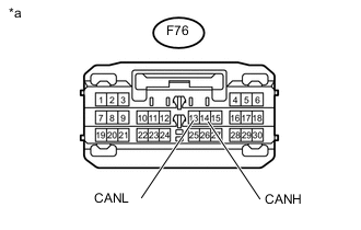
*a Front view of wire harness connector
(to Main Body ECU (Multiplex Network Body ECU))
-
Measure the resistance according to the value(s) in the table below.
Standard Resistance Tester Connection Switch Condition Specified Condition F76-14 (CANH) - F76-13 (CANL) Ignition switch off 54 to 69 Ω -
Reconnect the F76 main body ECU (multiplex network body ECU) connector.
OK
REPLACE MAIN BODY ECU (MULTIPLEX NETWORK BODY ECU) Click here
NG
REPAIR OR REPLACE CAN BUS BRANCH WIRE OR CONNECTOR (MAIN BODY ECU (MULTIPLEX NETWORK BODY ECU) BRANCH WIRE)
-
-
CHECK OPEN IN ONE SIDE OF CAN BRANCH WIRE (ENGINE STOP AND START ECU)
Tech Tips
For vehicles without stop and start system, go to step 15.
-
Disconnect the F131 engine stop and start ECU connector.
-
Select "Communication Bus Check" on the GTS Click here.
Result Result Proceed to "Stop and Go/Start" not displayed on the GTS. A Several ECUs and sensors other than "Stop and Go/Start" not displayed on the GTS. B
B
CHECK OPEN IN ONE SIDE OF CAN BRANCH WIRE (CERTIFICATION ECU (SMART KEY ECU ASSEMBLY)) Click here
A
-
-
CHECK OPEN IN ONE SIDE OF CAN BRANCH WIRE (ENGINE STOP AND START ECU BRANCH WIRE)
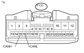
*a Front view of wire harness connector
(to Engine Stop and Start ECU)
-
Measure the resistance according to the value(s) in the table below.
Standard Resistance Tester Connection Switch Condition Specified Condition F131-15 (CANH) - F131-16 (CANL) Ignition switch off 54 to 69 Ω -
Reconnect the F131 engine stop and start ECU connector.
OK
REPLACE ENGINE STOP AND START ECU Click here
NG
REPAIR OR REPLACE CAN BUS BRANCH WIRE OR CONNECTOR (ENGINE STOP AND START ECU BRANCH WIRE)
-
-
CHECK OPEN IN ONE SIDE OF CAN BRANCH WIRE (CERTIFICATION ECU (SMART KEY ECU ASSEMBLY))
Tech Tips
For vehicles without entry and start system, go to step 17.
-
Disconnect the F63 certification ECU (smart key ECU assembly) connector.
-
Select "Communication Bus Check" on the GTS Click here.
Result Result Proceed to "Entry and Start/Wireless Tuner" not displayed on the GTS. A Several ECUs and sensors other than "Entry and Start/Wireless Tuner" not displayed on the GTS. B
B
CHECK OPEN IN ONE SIDE OF CAN BRANCH WIRE (OPTION CONNECTOR (BUS BUFFER ECU) BRANCH WIRE) Click here
A
-
-
CHECK OPEN IN ONE SIDE OF CAN BRANCH WIRE (CERTIFICATION ECU (SMART KEY ECU ASSEMBLY) BRANCH WIRE)
-
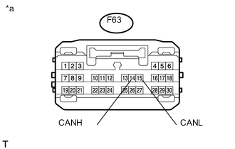
*a Front view of wire harness connector
(to Certification ECU (Smart Key ECU Assembly))
Measure the resistance according to the value(s) in the table below.
Standard Resistance Tester Connection Switch Condition Specified Condition F63-14 (CANH) - F63-15 (CANL) Ignition switch off 54 to 69 Ω -
Reconnect the F63 certification ECU (smart key ECU assembly) connector.
OK
REPLACE CERTIFICATION ECU (SMART KEY ECU ASSEMBLY)
NG
REPAIR OR REPLACE CAN BUS BRANCH WIRE OR CONNECTOR (CERTIFICATION ECU (SMART KEY ECU ASSEMBLY) BRANCH WIRE)
-
-
CHECK OPEN IN ONE SIDE OF CAN BRANCH WIRE (OPTION CONNECTOR (BUS BUFFER ECU) BRANCH WIRE)
Tech Tips
For vehicles without option connector (bus buffer ECU), go to step 18.
-
Disconnect the option connector (bus buffer ECU) assembly connector.
-
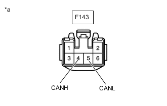
*a Rear view of wire harness connector
(to Option connector (bus buffer ECU))
Measure the resistance according to the value(s) in the table below.
Standard Resistance Tester Connection Switch Condition Specified Condition F143-4 (CANH) - F143-5 (CANL) Ignition switch off 54 to 69 Ω -
Reconnect the option connector (bus buffer ECU) assembly connector.
NG
REPLACE OPTION CONNECTOR (BUS BUFFER ECU)
OK
-
-
CHECK OPEN IN ONE SIDE OF CAN BRANCH WIRE (POWER STEERING ECU ASSEMBLY BRANCH WIRE)
-
Disconnect the power steering ECU assembly connector.
-
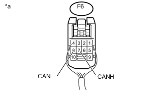
*a Rear view of wire harness connector
(to Power Steering ECU Assembly)
Measure the resistance according to the value(s) in the table below.
Standard Resistance Tester Connection Switch Condition Specified Condition F6-7 (CANH) - F6-8 (CANL) Ignition switch off 54 to 69 Ω Result Result Proceed to OK (for LHD) A OK (for RHD) B NG C -
Reconnect the F6 power steering ECU assembly connector.
A
REPLACE POWER STEERING ECU ASSEMBLY Click here
B
REPLACE POWER STEERING ECU ASSEMBLY Click here
C
REPAIR OR REPLACE CAN BUS BRANCH WIRE OR CONNECTOR (POWER STEERING ECU ASSEMBLY BRANCH WIRE)
-