CAN COMMUNICATION SYSTEM(w/o Toyota Safety Sense) Check CAN Bus Line for Short to GND (LHD Models)
DESCRIPTION
There may be a short circuit between the CAN bus lines and GND when the resistance between terminals 6 (CANH) and 4 (CG) or terminals 14 (CANL) and 4 (CG) of the DLC3 is below 200 Ω.
| Symptom | Trouble Area |
|---|---|
| The resistance between terminals 6 (CANH) and 4 (CG) or terminals 14 (CANL) and 4 (CG) of the DLC3 is below 200 Ω. |
|
-
*1: w/ Entry and Start System
-
*2: w/ VSC
-
*3: w/ Display
-
*4: w/ Air Conditioning System or PTC Heater
-
*5: w/ Stop and Start System
-
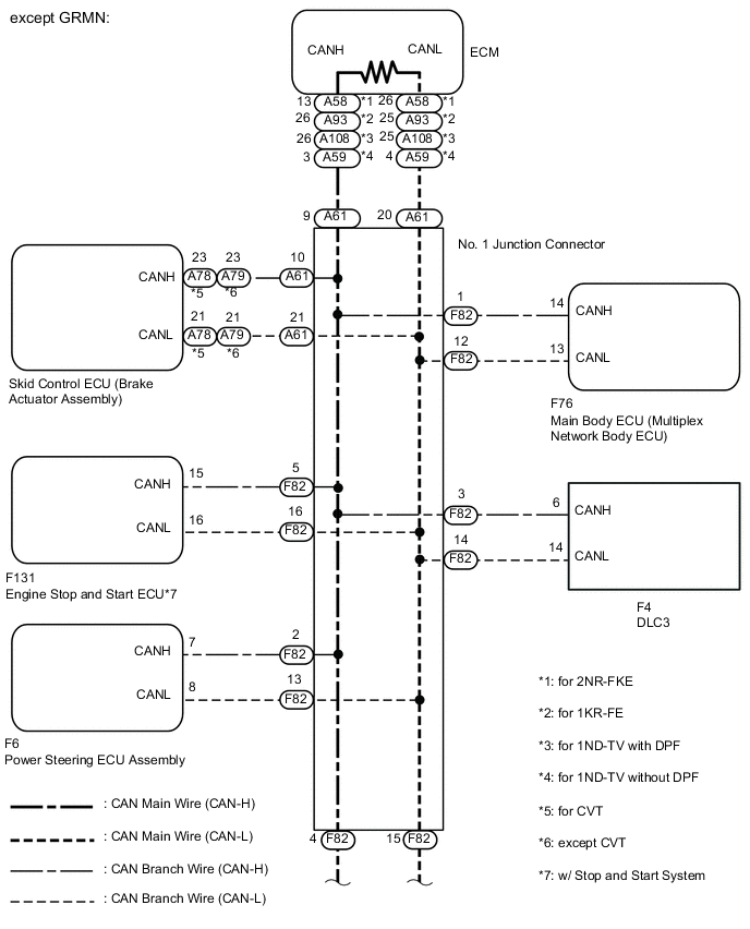
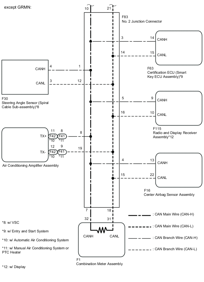
*6: except GRMN
-
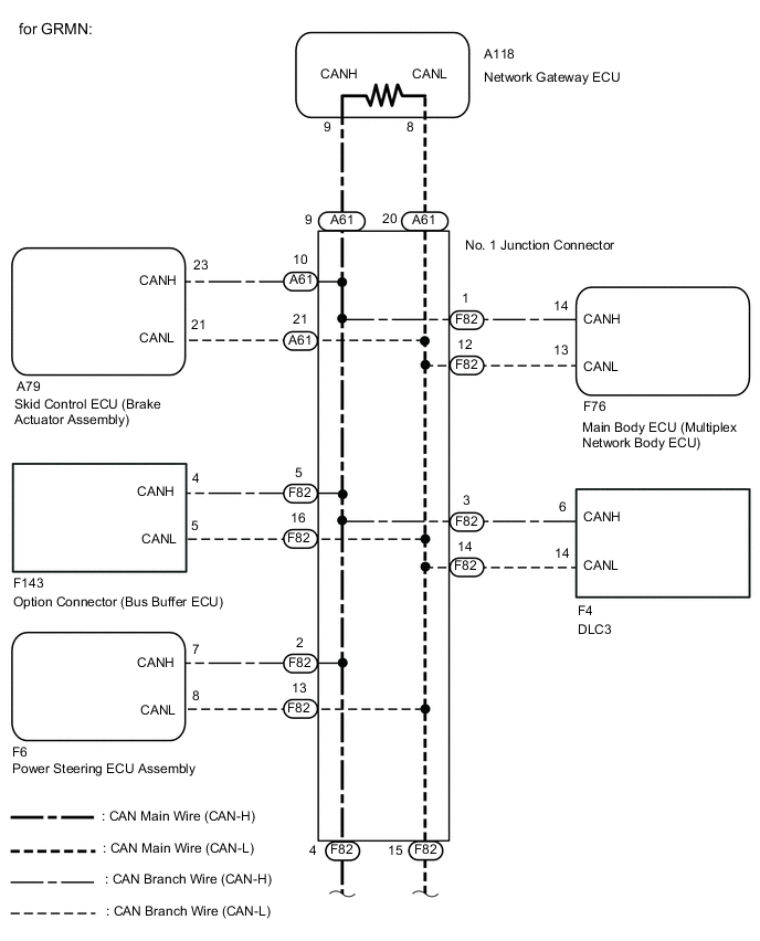
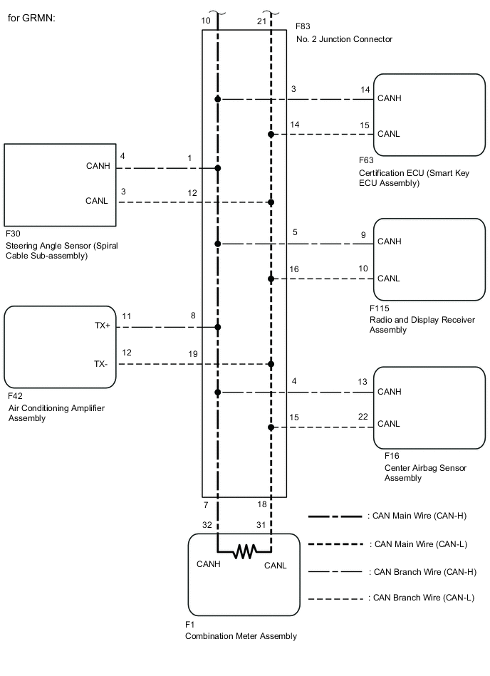
*6: for GRMN
WIRING DIAGRAM
CAUTION / NOTICE / HINT
Note
-
Turn the ignition switch off before measuring the resistances of the CAN main wire and the CAN branch wire.
-
After the ignition switch is turned off, check that the key reminder warning system and light reminder warning system are not in operation.
-
Before measuring the resistance, leave the vehicle as is for at least 1 minute and do not operate the ignition switch, any other switches or the doors. If doors need to be opened in order to check connectors, open the doors and leave them open.
Tech Tips
Operating the ignition switch, any switches or any doors triggers related ECU and sensor communication with the CAN, which causes resistance variation.
PROCEDURE
-
CHECK SHORT TO GND IN CAN BUS WIRE (DLC3 BRANCH WIRE)
-
Turn the ignition switch off.
-
Disconnect the A61 and F82 No. 1 junction connectors.
-
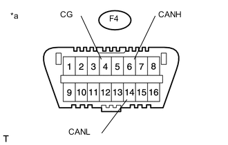
Text in Illustration *a Front view of DLC3 Measure the resistance according to the value(s) in the table below.
Standard Resistance Tester Connection Switch Condition Specified Condition F4-6 (CANH) - F4-4 (CG) Ignition switch off 200 Ω or higher F4-14 (CANL) - F4-4 (CG) Ignition switch off 200 Ω or higher
NG 
REPAIR OR REPLACE CAN BUS BRANCH WIRE OR CONNECTOR (DLC3 BRANCH WIRE)
OK 
-
-
CONNECT CONNECTOR
-
Reconnect the A61 and F82 No. 1 junction connectors.
NEXT
-
-
CHECK SHORT TO GND IN CAN BUS WIRE (NO. 2 JUNCTION CONNECTOR)
-
Disconnect the F83 No. 2 junction connector.
-
Text in Illustration *a Front view of DLC3 Measure the resistance according to the value(s) in the table below.
Standard Resistance Tester Connection Switch Condition Specified Condition F4-6 (CANH) - F4-4 (CG) Ignition switch off 200 Ω or higher F4-14 (CANL) - F4-4 (CG) Ignition switch off 200 Ω or higher
NG 
CHECK SHORT TO GND IN CAN BUS WIRE (NO. 1 JUNCTION CONNECTOR - NO. 2 JUNCTION CONNECTOR) Click here
OK
-
-
CHECK SHORT TO GND IN CAN BUS WIRE (NO. 2 JUNCTION CONNECTOR - COMBINATION METER ASSEMBLY)
-
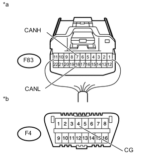
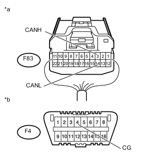
Text in Illustration *a Rear view of wire harness connector
(to No. 2 Junction Connector)
*b Front view of DLC3 Measure the resistance according to the value(s) in the table below.
Standard Resistance Tester Connection Switch Condition Specified Condition F83-7 (CANH) - F4-4 (CG) Ignition switch off 200 Ω or higher F83-18 (CANL) - F4-4 (CG) Ignition switch off 200 Ω or higher
NG
CHECK SHORT TO GND IN CAN BUS WIRE (COMBINATION METER ASSEMBLY MAIN WIRE) Click here
OK
-
-
CHECK SHORT TO GND IN CAN BUS WIRE (NO. 2 JUNCTION CONNECTOR - AIR CONDITIONING AMPLIFIER ASSEMBLY)
Tech Tips
For vehicles without air conditioning system or PTC heater, go to step 6.
-
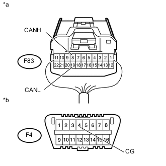
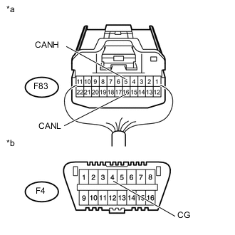
Text in Illustration *a Rear view of wire harness connector
(to No. 2 Junction Connector)
*b Front view of DLC3 Measure the resistance according to the value(s) in the table below.
Standard Resistance Tester Connection Switch Condition Specified Condition F83-8 (CANH) - F4-4 (CG) Ignition switch off 200 Ω or higher F83-19 (CANL) - F4-4 (CG) Ignition switch off 200 Ω or higher
NG
CHECK SHORT TO GND IN CAN BUS WIRE (AIR CONDITIONING AMPLIFIER ASSEMBLY BRANCH WIRE) Click here
OK
-
-
CHECK SHORT TO GND IN CAN BUS WIRE (NO. 2 JUNCTION CONNECTOR - STEERING ANGLE SENSOR (SPIRAL CABLE SUB-ASSEMBLY))
Tech Tips
For vehicles without VSC, go to step 7.
-
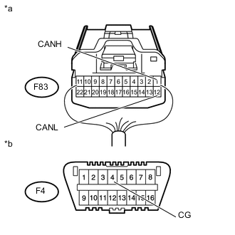
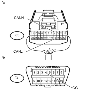
Text in Illustration *a Rear view of wire harness connector
(to No. 2 Junction Connector)
*b Front view of DLC3 Measure the resistance according to the value(s) in the table below.
Standard Resistance Tester Connection Switch Condition Specified Condition F83-1 (CANH) - F4-4 (CG) Ignition switch off 200 Ω or higher F83-12 (CANL) - F4-4 (CG) Ignition switch off 200 Ω or higher
NG
CHECK SHORT TO GND IN CAN BUS WIRE (STEERING ANGLE SENSOR (SPIRAL CABLE SUB-ASSEMBLY) BRANCH WIRE) Click here
OK
-
-
CHECK SHORT TO GND IN CAN BUS WIRE (NO. 2 JUNCTION CONNECTOR - CERTIFICATION ECU (SMART KEY ECU ASSEMBLY))
Tech Tips
For vehicles without entry and start system, go to step 8.
-
Text in Illustration *a Rear view of wire harness connector
(to No. 2 Junction Connector)
*b Front view of DLC3 Measure the resistance according to the value(s) in the table below.
Standard Resistance Tester Connection Switch Condition Specified Condition F83-3 (CANH) - F4-4 (CG) Ignition switch off 200 Ω or higher F83-14 (CANL) - F4-4 (CG) Ignition switch off 200 Ω or higher
NG
CHECK SHORT TO GND IN CAN BUS WIRE (CERTIFICATION ECU (SMART KEY ECU ASSEMBLY) BRANCH WIRE) Click here
OK
-
-
CHECK SHORT TO GND IN CAN BUS WIRE (NO. 2 JUNCTION CONNECTOR - RADIO AND DISPLAY RECEIVER ASSEMBLY)
Tech Tips
For vehicles without display, go to step 9.
-
Text in Illustration *a Rear view of wire harness connector
(to No. 2 Junction Connector)
*b Front view of DLC3 Measure the resistance according to the value(s) in the table below.
Standard Resistance Tester Connection Switch Condition Specified Condition F83-5 (CANH) - F4-4 (CG) Ignition switch off 200 Ω or higher F83-16 (CANL) - F4-4 (CG) Ignition switch off 200 Ω or higher
NG
CHECK SHORT TO GND IN CAN BUS WIRE (RADIO AND DISPLAY RECEIVER ASSEMBLY BRANCH WIRE Click here
OK
-
-
CHECK SHORT TO GND IN CAN BUS WIRE (NO. 2 JUNCTION CONNECTOR - CENTER AIRBAG SENSOR ASSEMBLY)
-
Text in Illustration *a Rear view of wire harness connector
(to No. 2 Junction Connector)
*b Front view of DLC3 Measure the resistance according to the value(s) in the table below.
Standard Resistance Tester Connection Switch Condition Specified Condition F83-4 (CANH) - F4-4 (CG) Ignition switch off 200 Ω or higher F83-15 (CANL) - F4-4 (CG) Ignition switch off 200 Ω or higher
OK
REPLACE NO. 2 JUNCTION CONNECTOR
NG
CHECK SHORT TO GND IN CAN BUS WIRE (CENTER AIRBAG SENSOR ASSEMBLY BRANCH WIRE) Click here
-
-
CHECK SHORT TO GND IN CAN BUS WIRE (NO. 1 JUNCTION CONNECTOR - NO. 2 JUNCTION CONNECTOR)
-
Disconnect the A61 and F82 No. 1 junction connectors.
-
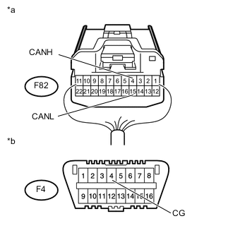
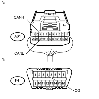
Text in Illustration *a Rear view of wire harness connector
(to No. 1 Junction Connector)
*b Front view of DLC3 Measure the resistance according to the value(s) in the table below.
Standard Resistance Tester Connection Switch Condition Specified Condition F82-4 (CANH) - F4-4 (CG) Ignition switch off 200 Ω or higher F82-15 (CANL) - F4-4 (CG) Ignition switch off 200 Ω or higher
NG
REPAIR OR REPLACE CAN BUS MAIN WIRE OR CONNECTOR (NO. 1 JUNCTION CONNECTOR - NO. 2 JUNCTION CONNECTOR)
OK
-
-
CONNECT CONNECTOR
-
Reconnect the F83 No. 2 junction connector.
NEXT
-
-
CHECK VEHICLE TYPE
-
Check vehicle type.
Result Result Proceed to except GRMN A for GRMN B
B
CHECK SHORT TO GND IN CAN BUS WIRE (NO. 1 JUNCTION CONNECTOR - NETWORK GATEWAY ECU) Click here
A
-
-
CHECK SHORT TO GND IN CAN BUS WIRE (NO. 1 JUNCTION CONNECTOR - ECM)
-
Text in Illustration *a Rear view of wire harness connector
(to No. 1 Junction Connector)
*b Front view of DLC3 Measure the resistance according to the value(s) in the table below.
Standard Resistance Tester Connection Switch Condition Specified Condition A61-9 (CANH) - F4-4 (CG) Ignition switch off 200 Ω or higher A61-20 (CANL) - F4-4 (CG) Ignition switch off 200 Ω or higher
OK
CHECK SHORT TO GND IN CAN BUS WIRE (NO. 1 JUNCTION CONNECTOR - SKID CONTROL ECU (BRAKE ACTUATOR ASSEMBLY) Click here
NG
CHECK SHORT TO GND IN CAN BUS WIRE (ECM MAIN WIRE) Click here
-
-
CHECK SHORT TO GND IN CAN BUS WIRE (NO. 1 JUNCTION CONNECTOR - NETWORK GATEWAY ECU)
-
Text in Illustration *a Rear view of wire harness connector
(to No. 1 Junction Connector)
*b Front view of DLC3 Measure the resistance according to the value(s) in the table below.
Standard Resistance Tester Connection Switch Condition Specified Condition A61-9 (CANH) - F4-4 (CG) Ignition switch off 200 Ω or higher A61-20 (CANL) - F4-4 (CG) Ignition switch off 200 Ω or higher
NG
CHECK SHORT TO GND IN CAN BUS WIRE (NETWORK GATEWAY ECU MAIN WIRE) Click here
OK
-
-
CHECK SHORT TO GND IN CAN BUS WIRE (NO. 1 JUNCTION CONNECTOR - SKID CONTROL ECU (BRAKE ACTUATOR ASSEMBLY)
-

Text in Illustration *a Rear view of wire harness connector
(to No. 1 Junction Connector)
*b Front view of DLC3 Measure the resistance according to the value(s) in the table below.
Standard Resistance Tester Connection Switch Condition Specified Condition A61-10 (CANH) - F4-4 (CG) Ignition switch off 200 Ω or higher A61-21 (CANL) - F4-4 (CG) Ignition switch off 200 Ω or higher
NG
CHECK SHORT TO GND IN CAN BUS WIRE (SKID CONTROL ECU (BRAKE ACTUATOR ASSEMBLY) BRANCH WIRE) Click here
OK
-
-
CHECK SHORT TO GND IN CAN BUS WIRE (NO. 1 JUNCTION CONNECTOR - ENGINE STOP AND START ECU)
Tech Tips
For vehicles without stop and start system, go to step 17.
-
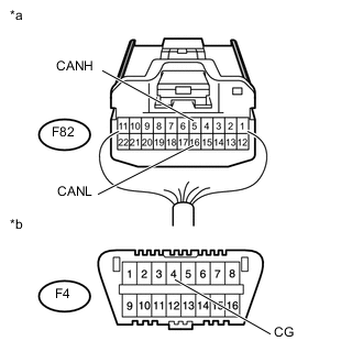
Text in Illustration *a Rear view of wire harness connector
(to No. 1 Junction Connector)
*b Front view of DLC3 Measure the resistance according to the value(s) in the table below.
Standard Resistance Tester Connection Switch Condition Specified Condition F82-5 (CANH) - F4-4 (CG) Ignition switch off 200 Ω or higher F82-16 (CANL) - F4-4 (CG) Ignition switch off 200 Ω or higher
NG
CHECK SHORT TO GND IN CAN BUS WIRE (ENGINE STOP AND START ECU BRANCH WIRE) Click here
OK
-
-
CHECK SHORT TO GND IN CAN BUS WIRE (NO. 1 JUNCTION CONNECTOR - OPTION CONNECTOR (BUS BUFFER ECU))
Tech Tips
For vehicles without option connector (bus buffer ECU), go to step 18.
-
Text in Illustration *a Rear view of wire harness connector
(to No. 1 Junction Connector)
*b Front view of DLC3 Measure the resistance according to the value(s) in the table below.
Standard Resistance Tester Connection Switch Condition Specified Condition F82-5 (CANH) - F4-4 (CG) Ignition switch off 200 Ω or higher F82-16 (CANL) - F4-4 (CG) Ignition switch off 200 Ω or higher
NG
CHECK SHORT TO GND IN CAN BUS WIRE (OPTION CONNECTOR (BUS BUFFER ECU) BRANCH WIRE) Click here
OK
-
-
CHECK SHORT TO GND IN CAN BUS WIRE (NO. 1 JUNCTION CONNECTOR - POWER STEERING ECU ASSEMBLY)
-
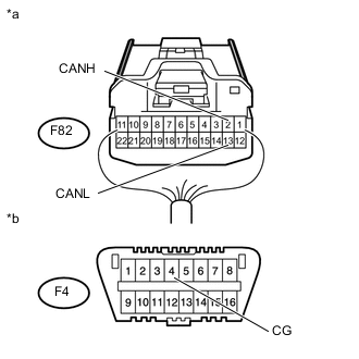
Text in Illustration *a Rear view of wire harness connector
(to No. 1 Junction Connector)
*b Front view of DLC3 Measure the resistance according to the value(s) in the table below.
Standard Resistance Tester Connection Switch Condition Specified Condition F82-2 (CANH) - F4-4 (CG) Ignition switch off 200 Ω or higher F82-13 (CANL) - F4-4 (CG) Ignition switch off 200 Ω or higher
NG
CHECK SHORT TO GND IN CAN BUS WIRE (POWER STEERING ECU ASSEMBLY) Click here
OK
-
-
CHECK SHORT TO GND IN CAN BUS WIRE (NO. 1 JUNCTION CONNECTOR - MAIN BODY ECU (MULTIPLEX NETWORK BODY ECU))
-
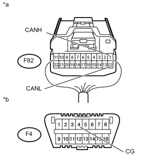
Text in Illustration *a Rear view of wire harness connector
(to No. 1 Junction Connector)
*b Front view of DLC3 Measure the resistance according to the value(s) in the table below.
Standard Resistance Tester Connection Switch Condition Specified Condition F82-1 (CANH) - F4-4 (CG) Ignition switch off 200 Ω or higher F82-12 (CANL) - F4-4 (CG) Ignition switch off 200 Ω or higher
OK
REPLACE NO. 1 JUNCTION CONNECTOR
NG
CHECK SHORT TO GND IN CAN BUS WIRE (MAIN BODY ECU (MULTIPLEX NETWORK BODY ECU) BRANCH WIRE) Click here
-
-
CHECK SHORT TO GND IN CAN BUS WIRE (COMBINATION METER ASSEMBLY MAIN WIRE)
-
Disconnect the F1 combination meter assembly connector.
-
Text in Illustration *a Rear view of wire harness connector
(to No. 2 Junction Connector)
*b Front view of DLC3 Measure the resistance according to the value(s) in the table below.
Standard Resistance Tester Connection Switch Condition Specified Condition F83-7 (CANH) - F4-4 (CG) Ignition switch off 200 Ω or higher F83-18 (CANL) - F4-4 (CG) Ignition switch off 200 Ω or higher
OK
REPLACE COMBINATION METER ASSEMBLY Click here
NG
REPAIR OR REPLACE CAN BUS MAIN WIRE OR CONNECTOR (COMBINATION METER ASSEMBLY MAIN WIRE)
-
-
CHECK SHORT TO GND IN CAN BUS WIRE (AIR CONDITIONING AMPLIFIER ASSEMBLY BRANCH WIRE)
-
Disconnect the F42*1 or F41*2 air conditioning amplifier assembly connector.
-
*1 : w/ Automatic Air Conditioning System
-
*2 : w/ Manual Air Conditioning System or PTC Heater
-
-
Text in Illustration *a Rear view of wire harness connector
(to No. 2 Junction Connector)
*b Front view of DLC3 Measure the resistance according to the value(s) in the table below.
Standard Resistance Tester Connection Switch Condition Specified Condition F83-8 (CANH) - F4-4 (CG) Ignition switch off 200 Ω or higher F83-19 (CANL) - F4-4 (CG) Ignition switch off 200 Ω or higher
OK
REPLACE AIR CONDITIONING AMPLIFIER ASSEMBLY Click here
NG
REPAIR OR REPLACE CAN BUS BRANCH WIRE OR CONNECTOR (AIR CONDITIONING AMPLIFIER ASSEMBLY BRANCH WIRE)
-
-
CHECK SHORT TO GND IN CAN BUS WIRE (STEERING ANGLE SENSOR (SPIRAL CABLE SUB-ASSEMBLY) BRANCH WIRE)
-
Disconnect the F30 steering angle sensor (spiral cable sub-assembly) connector.
-
Text in Illustration *a Rear view of wire harness connector
(to No. 2 Junction Connector)
*b Front view of DLC3 Measure the resistance according to the value(s) in the table below.
Standard Resistance Tester Connection Switch Condition Specified Condition F83-1 (CANH) - F4-4 (CG) Ignition switch off 200 Ω or higher F83-12 (CANL) - F4-4 (CG) Ignition switch off 200 Ω or higher
OK
REPLACE STEERING ANGLE SENSOR (SPIRAL CABLE SUB-ASSEMBLY) Click here
NG
REPAIR OR REPLACE CAN BUS BRANCH WIRE OR CONNECTOR (STEERING ANGLE SENSOR (SPIRAL CABLE SUB-ASSEMBLY) BRANCH WIRE)
-
-
CHECK SHORT TO GND IN CAN BUS WIRE (CERTIFICATION ECU (SMART KEY ECU ASSEMBLY) BRANCH WIRE)
-
Disconnect the F63 certification ECU (smart key ECU assembly) connector.
-
Text in Illustration *a Rear view of wire harness connector
(to No. 2 Junction Connector)
*b Front view of DLC3 Measure the resistance according to the value(s) in the table below.
Standard Resistance Tester Connection Switch Condition Specified Condition F83-3 (CANH) - F4-4 (CG) Ignition switch off 200 Ω or higher F83-14 (CANL) - F4-4 (CG) Ignition switch off 200 Ω or higher
OK
REPLACE CERTIFICATION ECU (SMART KEY ECU ASSEMBLY)
NG
REPAIR OR REPLACE CAN BUS BRANCH WIRE OR CONNECTOR (CERTIFICATION ECU (SMART KEY ECU ASSEMBLY) BRANCH WIRE)
-
-
CHECK SHORT TO GND IN CAN BUS WIRE (RADIO AND DISPLAY RECEIVER ASSEMBLY BRANCH WIRE
-
Disconnect the F115 radio and display receiver assembly connector.
-
Text in Illustration *a Rear view of wire harness connector
(to No. 2 Junction Connector)
*b Front view of DLC3 Measure the resistance according to the value(s) in the table below.
Standard Resistance Tester Connection Switch Condition Specified Condition F83-5 (CANH) - F4-4 (CG) Ignition switch off 200 Ω or higher F83-16 (CANL) - F4-4 (CG) Ignition switch off 200 Ω or higher
OK
REPLACE RADIO AND DISPLAY RECEIVER ASSEMBLY Click here
NG
REPAIR OR REPLACE CAN BUS BRANCH WIRE OR CONNECTOR (RADIO AND DISPLAY RECEIVER ASSEMBLY BRANCH WIRE)
-
-
CHECK SHORT TO GND IN CAN BUS WIRE (CENTER AIRBAG SENSOR ASSEMBLY BRANCH WIRE)
-
Disconnect the F16 center airbag sensor assembly connector.
-
Text in Illustration *a Rear view of wire harness connector
(to No. 2 Junction Connector)
*b Front view of DLC3 Measure the resistance according to the value(s) in the table below.
Standard Resistance Tester Connection Switch Condition Specified Condition F83-4 (CANH) - F4-4 (CG) Ignition switch off 200 Ω or higher F83-15 (CANL) - F4-4 (CG) Ignition switch off 200 Ω or higher
OK
REPLACE CENTER AIRBAG SENSOR ASSEMBLY Click here
NG
REPAIR OR REPLACE CAN BUS BRANCH WIRE OR CONNECTOR (CENTER AIRBAG SENSOR ASSEMBLY BRANCH WIRE)
-
-
CHECK SHORT TO GND IN CAN BUS WIRE (ECM MAIN WIRE)
-
Disconnect the A58*1, A93*2, A108*3 or A59*4 ECM connector.
-
*1: for 2NR-FKE
-
*2: for 1KR-FE
-
*3: for 1ND-TV with DPF
-
*4: for 1ND-TV without DPF
-
-
Text in Illustration *a Rear view of wire harness connector
(to No. 1 Junction Connector)
*b Front view of DLC3 Measure the resistance according to the value(s) in the table below.
Standard Resistance Tester Connection Switch Condition Specified Condition A61-9 (CANH) - F4-4 (CG) Ignition switch off 200 Ω or higher A61-20 (CANL) - F4-4 (CG) Ignition switch off 200 Ω or higher Result Result Proceed to NG A OK (for 2NR-FKE) B OK (for 1KR-FE) C OK (for 1ND-TV with DPF) D OK (for 1ND-TV without DPF) E
A
REPAIR OR REPLACE CAN BUS MAIN WIRE OR CONNECTOR (ECM MAIN WIRE)
B
REPLACE ECM Click here
C
REPLACE ECM Click here
D
REPLACE ECM Click here
E
REPLACE ECM Click here
-
-
CHECK SHORT TO GND IN CAN BUS WIRE (NETWORK GATEWAY ECU MAIN WIRE)
-
Disconnect the A118 network gateway ECU connector.
-
Text in Illustration *a Rear view of wire harness connector
(to No. 1 Junction Connector)
*b Front view of DLC3 Measure the resistance according to the value(s) in the table below.
Standard Resistance Tester Connection Switch Condition Specified Condition A61-9 (CANH) - F4-4 (CG) Ignition switch off 200 Ω or higher A61-20 (CANL) - F4-4 (CG) Ignition switch off 200 Ω or higher
OK
REPLACE NETWORK GATEWAY ECU Click here
NG
REPAIR OR REPLACE CAN BUS MAIN WIRE OR CONNECTOR (NETWORK GATEWAY ECU MAIN WIRE)
-
-
CHECK SHORT TO GND IN CAN BUS WIRE (SKID CONTROL ECU (BRAKE ACTUATOR ASSEMBLY) BRANCH WIRE)
-
Disconnect the A78*1 or A79*2 skid control ECU (brake actuator assembly) connector.
-
*1: for CVT
-
*2: except CVT
-
-
Text in Illustration *a Rear view of wire harness connector
(to No. 1 Junction Connector)
*b Front view of DLC3 Measure the resistance according to the value(s) in the table below.
Standard Resistance Tester Connection Switch Condition Specified Condition A61-10 (CANH) - F4-4 (CG) Ignition switch off 200 Ω or higher A61-21 (CANL) - F4-4 (CG) Ignition switch off 200 Ω or higher
OK
REPLACE SKID CONTROL ECU (BRAKE ACTUATOR ASSEMBLY) Click here
NG
REPAIR OR REPLACE CAN BUS BRANCH WIRE OR CONNECTOR (SKID CONTROL ECU (BRAKE ACTUATOR ASSEMBLY) BRANCH WIRE)
-
-
CHECK SHORT TO GND IN CAN BUS WIRE (ENGINE STOP AND START ECU BRANCH WIRE)
-
Disconnect the F131 engine stop and start ECU connector.
-
Text in Illustration *a Rear view of wire harness connector
(to No. 1 Junction Connector)
*b Front view of DLC3 Measure the resistance according to the value(s) in the table below.
Standard Resistance Tester Connection Switch Condition Specified Condition F82-5 (CANH) - F4-4 (CG) Ignition switch off 200 Ω or higher F82-16 (CANL) - F4-4 (CG) Ignition switch off 200 Ω or higher
OK
REPLACE ENGINE STOP AND START ECU Click here
NG
REPAIR OR REPLACE CAN BUS BRANCH WIRE OR CONNECTOR (ENGINE STOP AND START ECU BRANCH WIRE)
-
-
CHECK SHORT TO GND IN CAN BUS WIRE (OPTION CONNECTOR (BUS BUFFER ECU) BRANCH WIRE)
-
Disconnect the F143 option connector (bus buffer ECU) connector.
-
Text in Illustration *a Rear view of wire harness connector
(to No. 1 Junction Connector)
*b Front view of DLC3 Measure the resistance according to the value(s) in the table below.
Standard Resistance Tester Connection Switch Condition Specified Condition F82-5 (CANH) - F4-4 (CG) Ignition switch off 200 Ω or higher F82-16 (CANL) - F4-4 (CG) Ignition switch off 200 Ω or higher
OK
REPLACE OPTION CONNECTOR (BUS BUFFER ECU)
NG
REPAIR OR REPLACE CAN BUS BRANCH WIRE OR CONNECTOR (OPTION CONNECTOR (BUS BUFFER ECU) BRANCH WIRE)
-
-
CHECK SHORT TO GND IN CAN BUS WIRE (POWER STEERING ECU ASSEMBLY)
-
Disconnect the F6 power steering ECU assembly connector.
-
Text in Illustration *a Rear view of wire harness connector
(to No. 1 Junction Connector)
*b Front view of DLC3 Measure the resistance according to the value(s) in the table below.
Standard Resistance Tester Connection Switch Condition Specified Condition F82-2 (CANH) - F4-4 (CG) Ignition switch off 200 Ω or higher F82-13 (CANL) - F4-4 (CG) Ignition switch off 200 Ω or higher
OK
REPLACE POWER STEERING ECU ASSEMBLY Click here
NG
REPAIR OR REPLACE CAN BUS BRANCH WIRE OR CONNECTOR (POWER STEERING ECU ASSEMBLY BRANCH WIRE)
-
-
CHECK SHORT TO GND IN CAN BUS WIRE (MAIN BODY ECU (MULTIPLEX NETWORK BODY ECU) BRANCH WIRE)
-
Disconnect the F76 main body ECU (multiplex network body ECU) connector.
-
Text in Illustration *a Rear view of wire harness connector
(to No. 1 Junction Connector)
*b Front view of DLC3 Measure the resistance according to the value(s) in the table below.
Standard Resistance Tester Connection Switch Condition Specified Condition F82-1 (CANH) - F4-4 (CG) Ignition switch off 200 Ω or higher F82-12 (CANL) - F4-4 (CG) Ignition switch off 200 Ω or higher
OK
REPLACE MAIN BODY ECU (MULTIPLEX NETWORK BODY ECU) Click here
NG
REPAIR OR REPLACE CAN BUS BRANCH WIRE OR CONNECTOR (MAIN BODY ECU (MULTIPLEX NETWORK BODY ECU) BRANCH WIRE)
-