CAN COMMUNICATION SYSTEM(w/o Toyota Safety Sense) ECM Communication Stop Mode
DESCRIPTION
| Detection Item | Symptom | Trouble Area |
|---|---|---|
| ECM Communication Stop Mode | Either condition is met:
|
|
-
*1: for GRMN
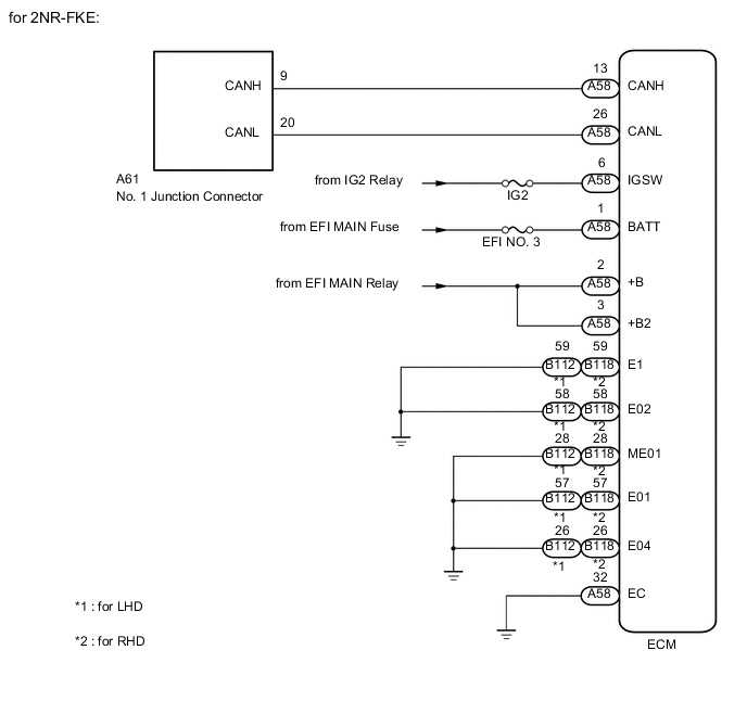
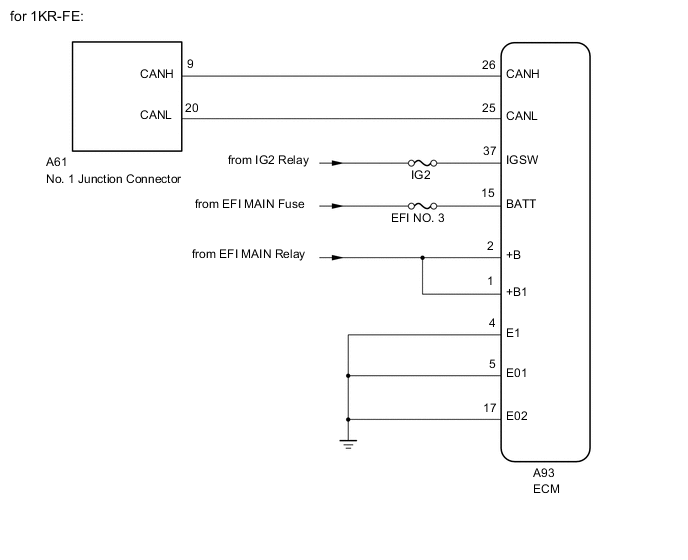
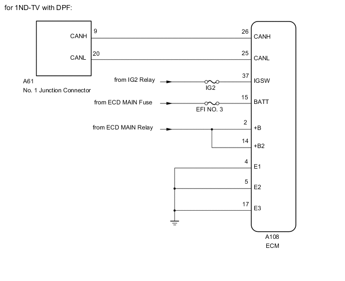
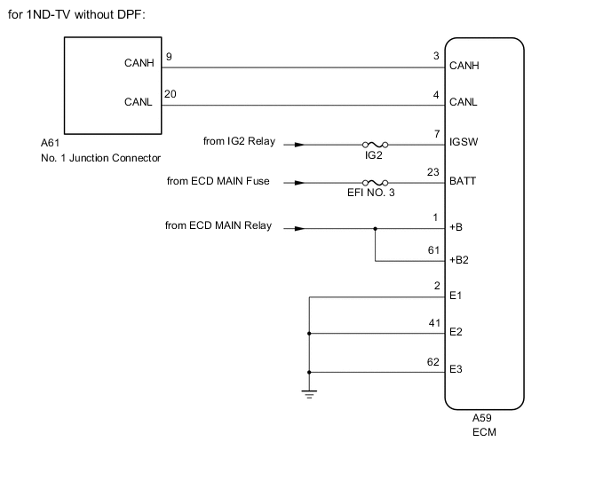
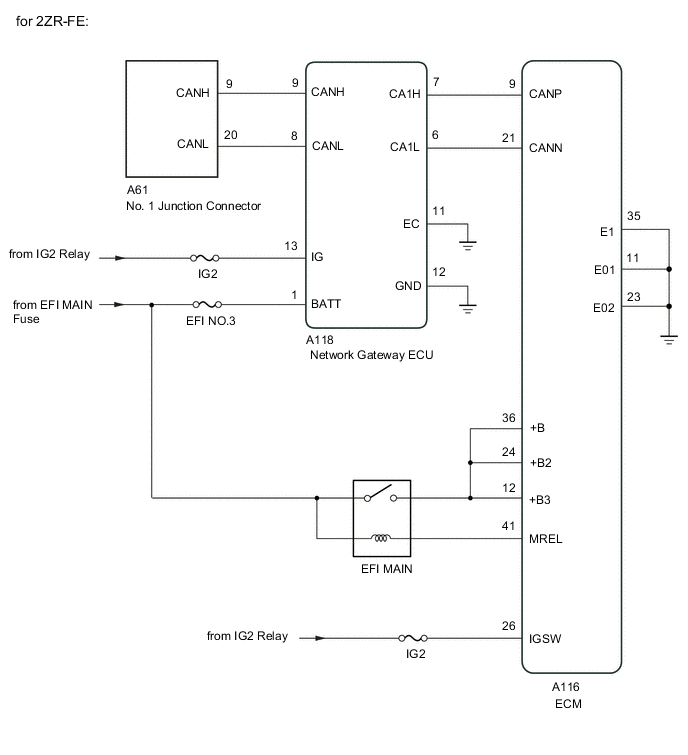
WIRING DIAGRAM
CAUTION / NOTICE / HINT
Note
-
Inspect the fuses for circuits related to this system before performing the following inspection procedure.
-
Turn the ignition switch off before measuring the resistances between CAN bus main wires and between CAN bus branch wires.
-
Turn the ignition switch off before inspecting CAN bus wires for a ground short.
-
After the ignition switch is turned off, check that the key reminder warning system are not operating.
-
Before measuring the resistance, leave the vehicle as is for at least 1 minute and do not operate the ignition switch, any other switches or the doors. If any doors need to be opened in order to check connectors, open the doors and leave them open.
Tech Tips
-
Operating the ignition switch, any other switches or a door triggers related ECU and sensor communication on the CAN. This communication will cause the resistance value to change.
-
Even after DTCs are cleared, if a DTC is stored again after driving the vehicle for a while, the malfunction may be occurring due to vibration of the vehicle. In such a case, wiggling the ECUs or wire harness while performing the inspection below may help determine the cause of the malfunction.
PROCEDURE
-
CHECK VEHICLE TYPE
-
Check vehicle type.
Result Result Proceed to except GRMN A for GRMN B
B 
CHECK OPEN IN CAN BUS MAIN WIRE (NETWORK GATEWAY ECU MAIN WIRE) Click here
A 
-
-
CHECK FOR OPEN IN CAN BUS MAIN WIRE (ECM MAIN WIRE)
-
Disconnect the ECM connector.
-
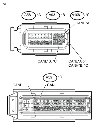
*A for 2NR-FKE *B for 1KR-FE *C for 1ND-TV with DPF *D for 1ND-TV without DPF *a Front view of wire harness connector
(to ECM)
Measure the resistance according to the value(s) in the table below.
Standard Resistance Tester Connection Switch Condition Specified Condition A58-13 (CANH) - A58-26 (CANL)*1
A93-26 (CANH) - A93-25 (CANL)*2
A108-26 (CANH) - A108-25 (CANL)*3
A59-3 (CANH) - A59-4 (CANL)*4
Ignition switch off 108 to 132 Ω *1: for 2NR-FKE
*2: for 1KR-FE
*3: for 1ND-TV with DPF
*4: for 1ND-TV without DPF
NG 
REPAIR OR REPLACE CAN BUS MAIN WIRE OR CONNECTOR (ECM MAIN WIRE)
OK
-
-
CHECK HARNESS AND CONNECTOR (POWER SOURCE CIRCUIT)
-
Check for the ECM power source circuit (for 2NR-FKE) Click here.
-
Check for the ECM power source circuit (for 1KR-FE) Click here.
-
Check for the ECM power source circuit (for 1ND-TV with DPF) Click here.
-
Check for the ECM power source circuit (for 1ND-TV without DPF) Click here
Result Result Proceed to OK (for 2NR-FKE) A OK (for 1KR-FE) B OK (for 1ND-TV with DPF) C OK (for 1ND-TV without DPF) D NG E
A
REPLACE ECM Click here
B
REPLACE ECM Click here
C
REPLACE ECM Click here
D
REPLACE ECM Click here
E
REPAIR OR REPLACE HARNESS OR CONNECTOR
-
-
CHECK OPEN IN CAN BUS MAIN WIRE (NETWORK GATEWAY ECU MAIN WIRE)
-
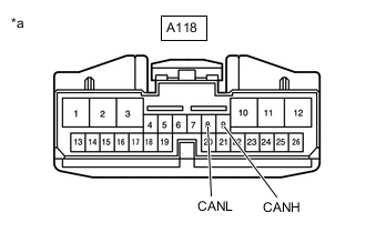
*a Front view of wire harness connector
(to Network Gateway ECU)
Disconnect the network gateway ECU assembly connector.
-
Measure the resistance according to the value(s) in the table below.
Standard Resistance Tester Connection Switch Condition Specified Condition A118-9 (CANH) - A118-8 (CANL) Ignition switch off 108 to 132 Ω
NG
REPAIR OR REPLACE HARNESS OR CONNECTOR
OK
-
-
CHECK HARNESS AND CONNECTOR (NETWORK GATEWAY ECU - BODY GROUND)
-
Disconnect the A118 network gateway ECU assembly connector.
-
Measure the resistance according to the value(s) in the table below.
Standard Resistance Tester Connection Condition Specified Condition A118-11 (EC) - Body ground Always Below 1 Ω A118-12 (GND) - Body ground Always Below 1 Ω
NG
REPAIR OR REPLACE HARNESS OR CONNECTOR
OK
-
-
CHECK NETWORK GATEWAY ECU (POWER SOURCE CIRCUIT)
-
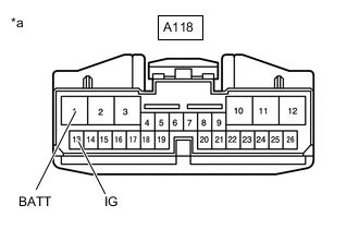
*a Front view of wire harness connector
(to Network Gateway ECU)
Disconnect the network gateway ECU assembly connector.
-
Measure the voltage according to the value(s) in the table below.
Standard Voltage Tester Connection Switch Condition Specified Condition A118-13 (IG) - Body ground Ignition switch ON 11 to 14 V A118-1 (BATT) - Body ground Always 11 to 14 V
NG
REPAIR OR REPLACE HARNESS OR CONNECTOR
OK
-
-
CHECK HARNESS AND CONNECTOR (ECM - BODY GROUND)
-
Disconnect the A116 ECM connector.
-
Measure the resistance according to the value(s) in the table below.
Standard Resistance Tester Connection Condition Specified Condition A116-11 (E01) - Body ground Always Below 1 Ω A116-23 (E02) - Body ground Always Below 1 Ω A116-35 (E1) - Body ground Always Below 1 Ω
NG
REPAIR OR REPLACE HARNESS OR CONNECTOR
OK
-
-
CHECK ECM (POWER SOURCE CIRCUIT)
-
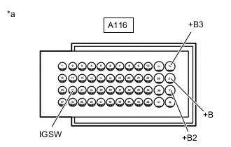
*a Front view of wire harness connector
(to ECM)
Disconnect the ECM connector.
-
Measure the voltage according to the value(s) in the table below.
Standard Voltage Tester Connection Switch Condition Specified Condition A116-26 (IGSW) - Body ground Ignition switch ON 11 to 14 V A116-36 (+B) - Body ground Ignition switch ON 11 to 14 V A116-24 (+B2) - Body ground Ignition switch ON 11 to 14 V A116-12 (+B3) - Body ground Ignition switch ON 11 to 14 V
NG
REPAIR OR REPLACE HARNESS OR CONNECTOR
OK
-
-
CHECK CHECK OPEN IN CAN LOCAL BUS WIRE (NETWORK GATEWAY ECU MAIN WIRE)
-
Reconnect the A116 ECM connector.
-
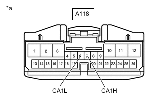
*a Front view of wire harness connector
(to Network Gateway ECU)
Disconnect the network gateway ECU connector.
Standard Resistance Tester Connection Switch Condition Specified Condition A118-7 (CA1H) - A118-6 (CA1L) Ignition switch off 108 to 132 Ω
NG
REPLACE NETWORK GATEWAY ECU Click here
OK
-
-
CHECK OPEN IN CAN LOCAL BUS WIRE (ECM MAIN WIRE)
-
Reconnect the A118 network gateway ECU connector.
-
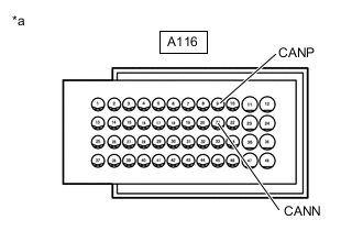
*a Front view of wire harness connector
(to ECM)
Disconnect the ECM connector.
Standard Resistance Tester Connection Switch Condition Specified Condition A116-9 (CANP) - A116-21 (CANN) Ignition switch off 108 to 132 Ω
OK
REPAIR OR REPLACE HARNESS OR CONNECTOR
NG
REPLACE ECM Click here
-