CAN COMMUNICATION SYSTEM(w/o Toyota Safety Sense) Open in CAN Main Bus Line (LHD Models)
DESCRIPTION
There may be an open circuit in the CAN main wire and/or DLC3 branch wire when the resistance between terminals 6 (CANH) and 14 (CANL) of the DLC3 is 69 Ω or higher.
| Symptom | Trouble Area |
|---|---|
| The resistance between terminals 6 (CANH) and 14 (CANL) of the DLC3 is 69 Ω or higher. |
|
-
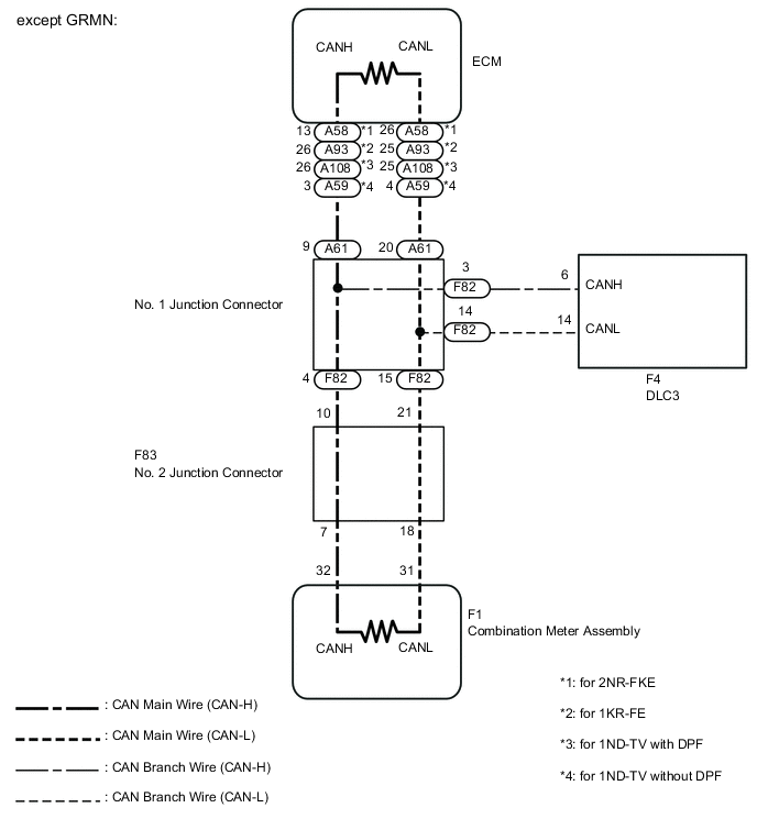
*1: except GRMN
-
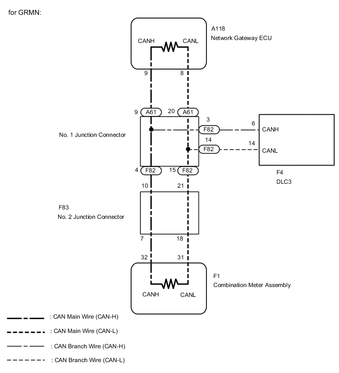
*1: for GRMN
WIRING DIAGRAM
CAUTION / NOTICE / HINT
Note
-
Turn the ignition switch off before measuring the resistances of the CAN main wire and the CAN branch wire.
-
After the ignition switch is turned off, check that the key reminder warning system and light reminder warning system are not in operation.
-
Before measuring the resistance, leave the vehicle as is for at least 1 minute and do not operate the ignition switch, any other switches or the doors. If doors need to be opened in order to check connectors, open the doors and leave them open.
Tech Tips
Operating the ignition switch, any switches or any doors triggers related ECU and sensor communication with the CAN, which causes resistance variation.
PROCEDURE
-
CHECK DLC3
-
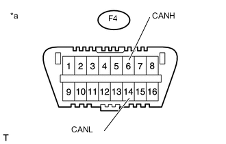
*a Front view of DLC3 Turn the ignition switch off.
-
Measure the resistance according to the value(s) in the table below.
Standard Resistance Tester Connection Switch Condition Specified Condition F4-6 (CANH) - F4-14 (CANL) Ignition switch off 108 to 132 Ω Tech Tips
When the measured value is 133 Ω or higher and a CAN communication system diagnostic trouble code is output, there may be a fault besides disconnection of the DLC3 branch wire. For that reason, troubleshooting should be performed again from "How to Proceed with Troubleshooting" Click here after repairing the trouble area.
NG 
REPAIR OR REPLACE CAN BUS BRANCH WIRE OR CONNECTOR (DLC3 BRANCH WIRE)
OK 
-
-
CHECK CAN MAIN WIRE OR CONNECTOR (NO. 2 JUNCTION CONNECTOR)
-
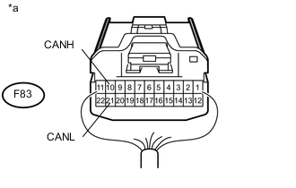
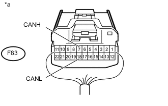
*a Rear view of wire harness connector
(to No. 2 Junction Connector)
Disconnect the No. 2 junction connector.
-
Measure the resistance according to the value(s) in the table below.
Standard Resistance Tester Connection Switch Condition Specified Condition F83-10 (CANH) - F83-21 (CANL) Ignition switch off 108 to 132 Ω
NG 
CONNECT CONNECTOR Click here
OK
-
-
CONNECT CONNECTOR
-
Reconnect the F83 No. 2 junction connector.
NEXT
-
-
CHECK CAN MAIN WIRE OR CONNECTOR (COMBINATION METER ASSEMBLY)
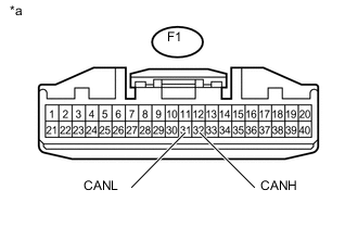
*a Front view of wire harness connector
(to Combination Meter Assembly)
-
Disconnect the combination meter assembly connector.
-
Measure the resistance according to the value(s) in the table below.
Standard Resistance Tester Connection Switch Condition Specified Condition F1-32 (CANH) - F1-31 (CANL) Ignition switch off 108 to 132 Ω
OK
REPLACE COMBINATION METER ASSEMBLY Click here
NG
-
-
CONNECT CONNECTOR
-
Reconnect the F1 combination meter assembly connector.
NEXT
-
-
CHECK CAN MAIN WIRE OR CONNECTOR (NO. 2 JUNCTION CONNECTOR - COMBINATION METER ASSEMBLY)
*a Rear view of wire harness connector
(to No. 2 Junction Connector)
-
Disconnect the No. 2 junction connector.
-
Measure the resistance according to the value(s) in the table below.
Standard Resistance Tester Connection Switch Condition Specified Condition F83-7 (CANH) - F83-18 (CANL) Ignition switch off 108 to 132 Ω Text in Illustration *a Rear view of wire harness connector
(to No. 2 Junction Connector)
OK
REPLACE NO. 2 JUNCTION CONNECTOR
NG
REPAIR OR REPLACE CAN MAIN WIRE OR CONNECTOR (NO. 2 JUNCTION CONNECTOR - COMBINATION METER ASSEMBLY)
-
-
CONNECT CONNECTOR
-
Reconnect the F83 No. 2 junction connector.
NEXT
-
-
CHECK VEHICLE TYPE
-
Check vehicle type.
Result Result Proceed to except GRMN A for GRMN B
B
CHECK CAN MAIN WIRE OR CONNECTOR (NETWORK GATEWAY ECU) Click here
A
-
-
CHECK CAN MAIN WIRE OR CONNECTOR (ECM)
-
Disconnect the ECM connector.
-
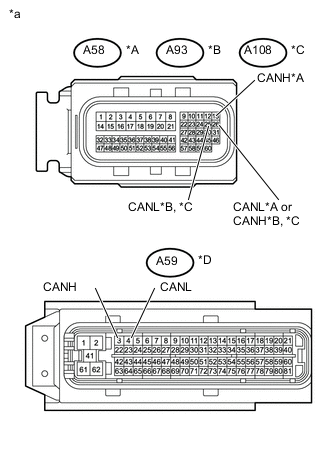
*A for 2NR-FKE *B for 1KR-FE *C for 1ND-TV with DPF *D for 1ND-TV without DPF *a Front view of wire harness connector
(to ECM)
Measure the resistance according to the value(s) in the table below.
Standard Resistance Tester Connection Switch Condition Specified Condition A58-13 (CANH) - A58-26 (CANL)*1
A93-26 (CANH) - A93-25 (CANL)*2
A108-26 (CANH) - A108-25 (CANL)*3
A59-3 (CANH) - A59-4 (CANL)*4
Ignition switch off 108 to 132 Ω *1: for 2NR-FKE
*2: for 1KR-FE
*3: for 1ND-TV with DPF
*4: for 1ND-TV without DPF
Result Result Proceed to NG A OK (for 2NR-FKE) B OK (for 1KR-FE) C OK (for 1ND-TV with DPF) D OK (for 1ND-TV without DPF) E
B
REPLACE ECM Click here
C
REPLACE ECM Click here
D
REPLACE ECM Click here
E
REPLACE ECM Click here
A
-
-
CONNECT CONNECTOR
-
Reconnect the A58*1, A93*2, A108*3 or A59*4 ECM connector.
*1: for 2NR-FKE
*2: for 1KR-FE
*3: for 1ND-TV with DPF
*4: for 1ND-TV without DPF
NEXT
-
-
CHECK CAN MAIN WIRE OR CONNECTOR (NO. 1 JUNCTION CONNECTOR - ECM)

*a Rear view of wire harness connector
(to No. 1 Junction Connector)
-
Disconnect the No. 1 junction connector.
-
Measure the resistance according to the value(s) in the table below.
Standard Resistance Tester Connection Switch Condition Specified Condition A61-9 (CANH) - A61-20 (CANL) Ignition switch off 108 to 132 Ω
NG
REPAIR OR REPLACE CAN MAIN WIRE OR CONNECTOR (ECM - NO. 1 JUNCTION CONNECTOR)
OK
-
-
CHECK CAN MAIN WIRE OR CONNECTOR (NO. 1 JUNCTION CONNECTOR - NO. 2 JUNCTION CONNECTOR)

*a Rear view of wire harness connector
(to No. 1 Junction Connector)
-
Measure the resistance according to the value(s) in the table below.
Standard Resistance Tester Connection Switch Condition Specified Condition F82-4 (CANH) - F82-15 (CANL) Ignition switch off 108 to 132 Ω
OK
REPLACE NO. 1 JUNCTION CONNECTOR
NG
REPAIR OR REPLACE CAN MAIN WIRE OR CONNECTOR (NO. 1 JUNCTION CONNECTOR - NO. 2 JUNCTION CONNECTOR)
-
-
CHECK CAN MAIN WIRE OR CONNECTOR (NETWORK GATEWAY ECU)
-
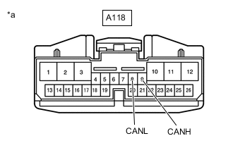
*a Front view of wire harness connector
(to Network Gateway ECU)
Disconnect the network gateway ECU connector.
-
Measure the resistance according to the value(s) in the table below.
Standard Resistance Tester Connection Switch Condition Specified Condition A118-9 (CANH) - A118-8 (CANL) Ignition switch off 108 to 132 Ω
NG
REPLACE NETWORK GATEWAY ECU Click here
OK
-
-
CONNECT CONNECTOR
-
Reconnect the A118 network gateway ECU connector.
NEXT
-
-
CHECK CAN MAIN WIRE OR CONNECTOR (NO. 1 JUNCTION CONNECTOR - NETWORK GATEWAY ECU)
-

*a Rear view of wire harness connector
(to No. 1 Junction Connector)
Disconnect the No. 1 junction connector.
-
Measure the resistance according to the value(s) in the table below.
Standard Resistance Tester Connection Switch Condition Specified Condition A61-9 (CANH) - A61-20 (CANL) Ignition switch off 108 to 132 Ω
NG
REPAIR OR REPLACE CAN MAIN WIRE OR CONNECTOR (NETWORK GATEWAY ECU - NO. 1 JUNCTION CONNECTOR)
OK
-
-
CHECK CAN MAIN WIRE OR CONNECTOR (NO. 1 JUNCTION CONNECTOR - NO. 2 JUNCTION CONNECTOR)
-
*a Rear view of wire harness connector
(to No. 1 Junction Connector)
Measure the resistance according to the value(s) in the table below.
Standard Resistance Tester Connection Switch Condition Specified Condition F82-4 (CANH) - F82-15 (CANL) Ignition switch off 108 to 132 Ω
OK
REPLACE NO. 1 JUNCTION CONNECTOR
NG
REPAIR OR REPLACE CAN MAIN WIRE OR CONNECTOR (NO. 1 JUNCTION CONNECTOR - NO. 2 JUNCTION CONNECTOR)
-