CAN COMMUNICATION SYSTEM(w/o Toyota Safety Sense) PRECAUTION
Note
After turning the ignition switch off, waiting time may be required before disconnecting the cable from the battery terminal. Therefore, make sure to read the disconnecting the cable from the battery terminal notice before proceeding with work Click here.
-
EXPRESSIONS OF IGNITION SWITCH
Tech Tips
The type of ignition switch used on this model differs according to the specifications of the vehicle. The expressions listed in the table below are used in this section.
Expression Ignition Switch
(Position)
Engine Switch
(Condition)
Ignition Switch off LOCK off Ignition Switch ON ON On (IG) Ignition Switch ACC ACC On (ACC) Engine Start START Start -
STEERING SYSTEM HANDLING PRECAUTIONS
-
Care must be taken when replacing parts. Incorrect replacement could affect the performance of the steering system and result in hazards when driving.
-
-
SRS AIRBAG SYSTEM HANDLING PRECAUTIONS
-
This vehicle is equipped with an SRS (Supplemental Restraint System), which includes components such as the driver airbag and front passenger airbag. Failure to carry out service operations in the correct sequence could cause unexpected SRS deployment during servicing and may lead to a serious accident. Before servicing (including installation/removal, inspection and replacement of parts), be sure to read the precautionary notice for the Supplemental Restraint System (See page SUPPLEMENTAL RESTRAINT SYSTEMS > AIRBAG SYSTEM (w/ VSC) > PRECAUTION).
-
-
BUS LINE REPAIR
-
After repairing the bus line with solder, wrap the repaired part with vinyl tape Click here.
Note
-
The CANL bus line and CANH bus line must be installed together.
-
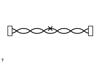
When installing the CAN bus lines, be sure to twist them.
-
CAN bus lines are likely to be influenced by noise if the bus lines are not twisted together.
-
Leave approximately 80 mm (3.15 in.) loose in the twisted wires around the connectors.
-
When repairing the CAN bus lines, do not change the length of the lines. (Make sure that the length of the CANH bus line and CANL bus line are the same.)
-
-
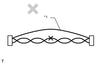
Text in Illustration *1 By-pass Wire Do not use by-pass wiring between the connectors.
Note
The protective effect of the twisted wire harness is lost if bypass wiring is used.
-
-
CONNECTOR HANDLING
-
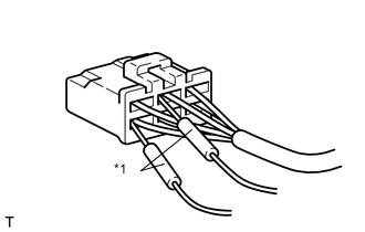
Text in Illustration *1 Tester Probe When inserting probes into a connector, insert them from the rear of the connector.
-
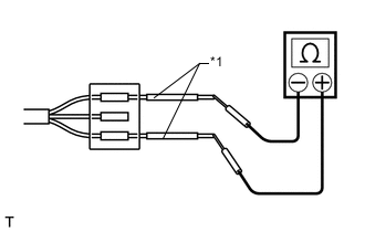
Text in Illustration *1 Repair Wire Use a repair wire to check the connector if it is impossible to check resistance from the rear of the connector.
-
-
PRECAUTIONS FOR INSPECTING OR REPLACING CAN JUNCTION CONNECTOR
-
If the CAN junction connector is removed from the vehicle for inspection or replacement, make sure to install the CAN junction connector and all wire harnesses to their original locations with tape and the clamps.
-