CAN COMMUNICATION SYSTEM(w/ Toyota Safety Sense) Check Bus 2 Lines for Short Circuit
DESCRIPTION
There may be a short circuit between the bus 2 main lines and/or CAN branch lines when the resistance between terminals 18 (CA4H) and 17 (CA4L) of the central gateway ECU (network gateway ECU) is below 54 Ω.
| Symptom | Trouble Area |
|---|---|
| Resistance between terminals 18 (CA4H) and 17 (CA4L) of central gateway ECU (network gateway ECU) is below 54 Ω. |
|
-
*1: w/ Entry and Start System
-
*2: w/ Air Conditioning System or PTC Heater
-
*3: w/ Stop and Start System
WIRING DIAGRAM
CAUTION / NOTICE / HINT
Note
-
Turn the ignition switch off before measuring the resistances of the CAN main wire and the CAN branch wire.
-
After the ignition switch is turned off, check that the key reminder warning system and light reminder warning system are not in operation.
-
Before measuring the resistance, leave the vehicle as is for at least 1 minute and do not operate the ignition switch, any other switches or the doors. If doors need to be opened in order to check connectors, open the doors and leave them open.
Tech Tips
Operating the ignition switch, any switches or any doors triggers related ECU and sensor communication with the CAN, which causes resistance variation.
PROCEDURE
-
CHECK FOR SHORT IN CAN BUS LINES (COMBINATION METER ASSEMBLY - NO. 2 JUNCTION CONNECTOR)
-
Disconnect the cable from the negative (-) battery terminal.
-
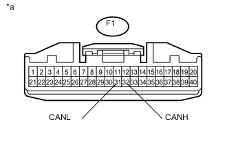
Text in Illustration *a Front view of wire harness connector
(to Combination Meter Assembly)
Disconnect the combination meter assembly connector.
-
Measure the resistance according to the value(s) in the table below.
Standard Resistance Tester Connection Condition Specified Condition F1-32 (CANH) - F1-31 (CANL) Cable disconnected from negative (-) battery terminal 108 to 132 Ω Tech Tips
If the resistance becomes normal (between 108 to 132 Ω) when the connector is disconnected, there may be a short in the combination meter assembly.
OK 
REPLACE COMBINATION METER ASSEMBLY Click here
NG 
-
-
CHECK FOR SHORT IN CAN BUS LINES (ECM MAIN BUS LINE - NO. 1 JUNCTION CONNECTOR)
-
Reconnect the F1 combination meter assembly connector.
-
Disconnect the ECM connector.
-
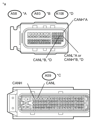
Text in Illustration *A for 2NR-FKE *B for 1KR-FE *C for 1ND-TV without DPF *D for 1ND-TV with DPF *a Front view of wire harness connector
(to ECM)
Measure the resistance according to the value(s) in the table below.
Standard Resistance Tester Connection Condition Specified Condition A58-13 (CANH) - A58-26 (CANL)*1
A93-26 (CANH) - A93-25 (CANL)*2
A59-3 (CANH) - A59-4 (CANL)*3
A108-26 (CANH) - A108-25 (CANL)*4
Cable disconnected from negative (-) battery terminal 108 to 132 Ω *1: for 2NR-FKE
*2: for 1KR-FE
*3: for 1ND-TV without DPF
*4: for 1ND-TV with DPF
Result Result Proceed to NG A OK (for 2NR-FKE) B OK (for 1KR-FE) C OK (for 1ND-TV with DPF) D OK (for 1ND-TV without DPF) E Tech Tips
If the resistance becomes normal (between 108 to 132 Ω) when the connector is disconnected, there may be a short in the ECM.
B
REPLACE ECM Click here
C
REPLACE ECM Click here
D
REPLACE ECM Click here
E
REPLACE ECM Click here
A
-
-
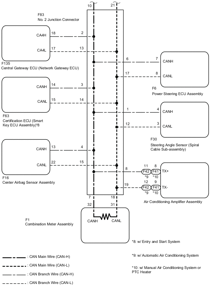
CHECK FOR SHORT IN CAN BUS LINES (NO. 2 JUNCTION CONNECTOR)
-
Reconnect the A58*1, A93*2, A59*3 or A108*4 ECM connector.
*1: for 2NR-FKE
*2: for 1KR-FE
*3: for 1ND-TV without DPF
*4: for 1ND-TV with DPF
-
Disconnect the No. 2 junction connector.
-
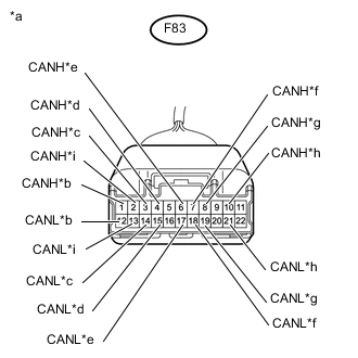
Text in Illustration *a Front view of wire harness connector
(to No. 2 Junction Connector)
*b to Steering Angle Sensor (Spiral Cable Sub-assembly) *c to Certification ECU (Smart Key ECU Assembly) (w/ Entry and Start System) *d to Center Airbag Sensor Assembly *e to Power Steering ECU Assembly *f to Combination Meter Assembly *g to Air Conditioning Amplifier Assembly (w/ Air Conditioning System or PTC Heater) *h to No. 1 Junction Connector *i to Central Gateway ECU (Network Gateway ECU) Measure the resistance according to the value(s) in the table below.
Standard Resistance Tester Connection Condition Specified Condition Connected to F83-1 (CANH) - F83-12 (CANL) Cable disconnected from negative (-) battery terminal 200 Ω or higher Steering angle sensor (Spiral cable sub-assembly) F83-3 (CANH) - F83-14 (CANL) Cable disconnected from negative (-) battery terminal 200 Ω or higher Certification ECU (Smart key ECU assembly)*1 F83-4 (CANH) - F83-15 (CANL) Cable disconnected from negative (-) battery terminal 200 Ω or higher Center airbag sensor assembly F83-6 (CANH) - F83-17 (CANL) Cable disconnected from negative (-) battery terminal 200 Ω or higher Power steering ECU assembly F83-7 (CANH) - F83-18 (CANL) Cable disconnected from negative (-) battery terminal 108 to 132 Ω Combination meter assembly F83-8 (CANH) - F83-19 (CANL) Cable disconnected from negative (-) battery terminal 200 Ω or higher Air conditioning amplifier assembly*2 F83-10 (CANH) - F83-21 (CANL) Cable disconnected from negative (-) battery terminal 108 to 132 Ω No. 1 junction connector F83-2 (CANH) - F83-13 (CANL) Cable disconnected from negative (-) battery terminal 200 Ω or higher Central gateway ECU (network gateway ECU)
-
*1: w/ Entry and Start System
-
*2: w/ Air Conditioning System or PTC Heater
Result Result Proceed to OK A NG (No. 1 junction connector main line) B NG (ECU or sensor branch line) C NG (Combination meter assembly main line) D NG (Central gateway ECU (network gateway ECU) branch line) E -
A
REPLACE NO. 2 JUNCTION CONNECTOR
C 
CHECK FOR SHORT IN CAN BUS LINES (ECU, SENSOR) Click here
D
REPAIR OR REPLACE CAN MAIN BUS LINES (COMBINATION METER ASSEMBLY - NO. 2 JUNCTION CONNECTOR)
E
REPAIR OR REPLACE CAN BRANCH LINE CONNECTED TO CENTRAL GATEWAY ECU (NETWORK GATEWAY ECU)
B
-
-
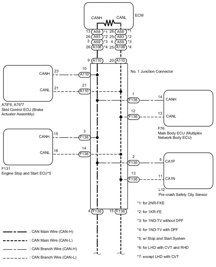
CHECK FOR SHORT IN CAN BUS LINES (NO. 1 JUNCTION CONNECTOR)
-
Disconnect the No. 1 junction connector.
-
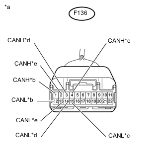
Text in Illustration *a Front view of wire harness connector
(to No. 1 Junction Connector)
*b to Main Body ECU (Multiplex Network Body ECU) *c to No. 2 Junction Connector *d to Engine Stop and Start ECU (w/ Stop and Start System) *e to Pre-crash Safety City Sensor Measure the resistance according to the value(s) in the table below.
Standard Resistance Tester Connection Condition Specified Condition Connected to F136-1 (CANH) - F136-12 (CANL) Cable disconnected from negative (-) battery terminal 200 Ω or higher Main body ECU (Multiplex network body ECU) F136-4 (CANH) - F136-15 (CANL) Cable disconnected from negative (-) battery terminal 108 to 132 Ω No. 2 junction connector F136-3 (CANH) - F136-14 (CANL) Cable disconnected from negative (-) battery terminal 200 Ω or higher Engine stop and start ECU*1 F136-2 (CANH) - F136-13 (CANL) Cable disconnected from negative (-) battery terminal 200 Ω or higher Pre-crash safety city sensor
-
*1: w/ Stop and Start System
Result Result Proceed to OK A NG (No. 2 junction connector main line) B NG (ECU or sensor branch line) C -
B
REPAIR OR REPLACE CAN MAIN BUS LINES (NO. 1 JUNCTION CONNECTOR - NO. 2 JUNCTION CONNECTOR)
C
CHECK FOR SHORT IN CAN BUS LINES (ECU, SENSOR) Click here
A
-
-
CHECK FOR SHORT IN CAN BUS LINES (NO. 1 JUNCTION CONNECTOR)
-
Disconnect the No. 1 junction connector.
-
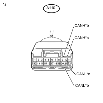
Text in Illustration *a Front view of wire harness connector
(to No. 1 Junction Connector)
*b to ECM *c to Skid Control ECU (Brake Actuator Assembly) Measure the resistance according to the value(s) in the table below.
Standard Resistance Tester Connection Condition Specified Condition Connected to A110-9 (CANH) - A110-20 (CANL) Cable disconnected from negative (-) battery terminal 108 to 132 Ω ECM A110-10 (CANH) - A110-21 (CANL) Cable disconnected from negative (-) battery terminal 200 Ω or higher Skid control ECU (Brake actuator assembly) Result Result Proceed to OK A NG (ECM main line) B NG (ECU or sensor branch line) C
A
REPLACE NO. 1 JUNCTION CONNECTOR
B
REPAIR OR REPLACE CAN MAIN BUS LINES (ECM - NO. 1 JUNCTION CONNECTOR)
C
-
-
CHECK FOR SHORT IN CAN BUS LINES (ECU, SENSOR)
-
Reconnect all wire harness connectors (No. 1 junction connector and No. 2 junction connector).
-
Disconnect the connector that includes terminals CANH and CANL from the ECU (or sensor) to which the short circuited branch line is connected Click here.
-
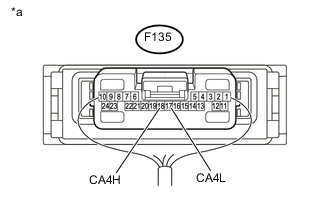
Text in Illustration *a Component with harness connected
(Central Gateway ECU (Network Gateway ECU))
Measure the resistance according to the value(s) in the table below.
Standard Resistance Tester Connection Condition Specified Condition F135-18 (CA4H) - F135-17 (CA4L) Cable disconnected from negative (-) battery terminal 54 to 69 Ω Tech Tips
If the resistance becomes normal (between 54 and 69 Ω) when the connector is disconnected from the ECU (or sensor), there may be a short in the ECU (or sensor).
OK
REPLACE CORRESPONDING ECU OR SENSOR
NG
REPAIR OR REPLACE CORRESPONDING ECU OR SENSOR BRANCH LINES OR CONNECTOR
-