CAN COMMUNICATION SYSTEM(w/ Toyota Safety Sense) DIAGNOSIS SYSTEM
-
ECUS OR SENSORS WHICH COMMUNICATE THROUGH CAN COMMUNICATION SYSTEM
-
V Bus
-
Central gateway ECU (network gateway ECU)
-
-
Bus 2
-
ECM
-
Skid control ECU (brake actuator assembly)
-
Main body ECU (Multiplex network body ECU)
-
Air conditioning amplifier assembly*1
-
Power steering ECU assembly
-
Certification ECU (smart key ECU assembly)*2
-
Center airbag sensor assembly
-
Steering angle sensor (spiral cable sub-assembly)
-
Engine Stop and Start ECU*3
-
Pre-crash safety city sensor
-
Combination meter assembly
-
*1: w/ Air Conditioning System or PTC Heater
-
*2: w/ Entry and Start System
-
*3: w/ Stop and Start System
-
-
-
Bus 3
-
Radio and display receiver assembly*1
-
*1: w/ Display
-
-
-
-
CHECK FOR INSTALLED SYSTEMS (ECUS AND SENSORS) THAT ADOPT CAN COMMUNICATION
-
The systems (ECUs and sensors) that adopt CAN communication vary depending on the vehicle and optional equipment. Check which systems (ECUs and sensors) are installed on the vehicle.
Tech Tips
The names of ECUs and sensors shown on the GTS display may differ from those shown in the DTC Table by ECU section that follows.
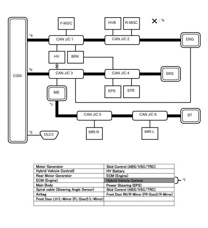
ECU/Sensor Name GTS Display Applicability Central gateway ECU (network gateway ECU) CAN Gateway1 Installed on all vehicles Air conditioning amplifier assembly Air Conditioning Amplifier w/ Air Conditioning System or PTC Heater Center airbag sensor assembly Airbag All vehicles Combination meter assembly Combination Meter All vehicles Radio and Display Receiver Assembly Display and Navigation (AVN1) w/ Display ECM ECM (Engine) All vehicles Certification ECU (smart key ECU assembly) Certification (Smart) w/ Entry and Start System Main body ECU (multiplex network body ECU) Main Body All vehicles Engine stop and start ECU Stop & Go w/ Stop and Start System Power steering ECU assembly Power Steering (EPS) All vehicles Skid control ECU (brake actuator assembly) Skid Control (ABS/VSC/TRC) All vehicles Steering angle sensor (spiral cable sub-assembly) Spiral cable (Steering Angle Sensor) All vehicles Pre-crash safety city sensor Front Camera Module Installed on all vehicles
-
-
CAN BUS CHECK
Tech Tips
The ECUs and sensors that are properly connected to the CAN communication system can be displayed using the GTS.
-
Using the GTS, select the CAN Bus Check screen.
Note
-
It may be possible to select buses that do not have ECUs or sensors from the bus selection pull-down menu. This is not a malfunction. (This occurs when optional devices are not on a sub bus that is monitored by a gateway function equipped ECU.)
-
In the bus selection pull down menu, all buses applicable to the model are displayed (e.g. LIN communication buses are also displayed). Therefore, refer to the wiring diagrams to check the names of sub buses for CAN communication.
Tech Tips
Different connection statuses are indicated by the background color of ECUs and sensors that are displayed.
Explanation of CAN Bus Check Screen Bus Type Background Color Connection Status Bus White Communication has been normal. Yellow Communication stop occurred at least once since the start of the CAN bus check, but communication is currently occurring (unstable communication). Red Currently not communicating (either of the following):
-
Not communicating since the start of the CAN bus check
-
Communication occurred at least once since the start of the CAN bus check, but is currently not occurring.
Not displayed Either of the following:
-
The central gateway ECU (network gateway ECU) has an internal malfunction or cannot communicate with the GTS.*4
-
No ECUs or sensors are connected to the bus.*5
Sub bus with a gateway function equipped ECU that does not memorize connected ECUs or sensors*2 White Communication has been normal since the start of the CAN bus check. Yellow Communication stop occurred at least once since the start of the CAN bus check, but communication is currently occurring (unstable communication). Red Communication occurred at least once since the start of the CAN bus check, but is currently not occurring. Not displayed Communication stop has continued since the start of the CAN bus check.*1 Sub bus with a gateway function equipped ECU that memorizes connected ECUs and sensors*3 White Communication has been normal. Yellow Communication stop occurred at least once since the start of the CAN bus check, but communication is currently occurring (unstable communication). Red Currently not communicating (either of the following):
-
Not communicating since the start of the CAN bus check
-
Communication occurred at least once since the start of the CAN bus check, but is currently not occurring.
Not displayed Either of the following:
-
The gateway function equipped ECU cannot communicate with the central gateway ECU.*6
-
No ECUs or sensors are connected to the sub bus.*7
-
Gateway function equipped ECUs relay signals between ECUs and sensors connected to different buses.
-
*1: An ECU or sensor is installed to the vehicle but is not displayed on the "Communication Bus Check" screen.
-
*2: The gateway function equipped ECU does not memorize ECUs and sensors connected to its respective sub bus.
-
*3: The gateway function equipped ECU memorizes ECUs and sensors connected to its respective sub bus.
-
*4: When the central gateway ECU has an internal malfunction or cannot communicate with the GTS, the name of buses, sub buses, ECUs and sensors will not be displayed.
-
*5: When no ECUs or sensors are connected to a bus, the message "There is no system found on the communication Bus." will be displayed.
-
*6: When a gateway function equipped ECU cannot communicate with the central gateway ECU, the name of sub buses and ECUs or sensors connected to the sub bus will not be displayed.
-
*7: When no ECUs or sensors are connected to the sub bus, the message "There is no system found on the communication Bus." will be displayed.
-
If there is no communication between the GTS and the vehicle, or no ECUs or sensors are displayed as connected, check the central gateway ECU and V bus (the bus that connects the DLC3 to the central gateway ECU) for malfunctions.
-
-
Observe the connection response screen for approximately 2 minutes to check for a change in connection status of the connected ECUs and sensors.
Tech Tips
-
If an open occurs in one of the lines of a CAN branch (except DLC3), output from the other branch line (the line that is not open) will be unstable and it may interfere with the response (display) of other ECUs and sensors.
-
If the connection status changes during the inspection, repair the open in the branch line of the ECU or sensor that does not respond (is not detected) and then perform the CAN bus check again.
-
-
-
HOW TO INTERPRET CAN BUS CHECK SCREEN
-
When a communication stop is currently occurring, the probable malfunctioning part can be determined from the CAN bus check and by using the following methods.
Note
The following CAN bus wiring diagram is provided only as an example. This wiring diagram is different from the actual wiring diagram for this vehicle.
Tech Tips
-
When a communication stop is currently occurring, it is easier to determine the probable malfunctioning part from the CAN bus check rather than from communication DTCs.
-
Wait for approximately 2 minutes after turning the ignition switch ON (or simulate the driving conditions that enable the malfunction to be reproduced) and select "CAN Bus Check". Then observe the communication status of each ECU on the screen.
-
-
If a communication error of only 1 ECU or sensor is indicated on the CAN Bus Check screen, a communication stop of the ECU or sensor is suspected.
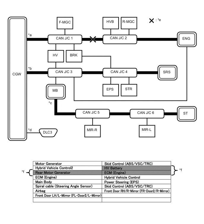
Open in both CAN branch lines of HV on the bus 4
*a Bus 2 *b Bus 4 *c Sub Bus *d V Bus *e Location of Malfunction *f Background color is red Tech Tips
When there are communication stops, ECUs that are present in the vehicle may not be displayed on the CAN Bus Check screen.
-
If communication errors for multiple ECUs or sensors are indicated on the CAN Bus Check screen, then a communication stop of the ECU or sensor that shows a more serious communication stop (an ECU or sensor whose background color is red) is suspected.
Example: Open in a CAN branch line for HV on the bus 4
*a Background color is red *b Background color intermittently becomes yellow or red *c Not displayed or background color is yellow or red - - Explanation of CAN Bus Check Screen Bus Type Background Color Connection Status Bus White Communication has been normal. Yellow Communication stop occurred at least once since the start of the CAN bus check, but communication is currently occurring (unstable communication). Red Currently not communicating (either of the following):
-
Not communicating since the start of the CAN bus check
-
Communication occurred at least once since the start of the CAN bus check, but is currently not occurring.
Not displayed Either of the following:
-
The central gateway ECU (network gateway ECU) has an internal malfunction or cannot communicate with the GTS.*4
-
No ECUs or sensors are connected to the bus.*5
Sub bus with a gateway function equipped ECU that does not memorize connected ECUs or sensors*2 White Communication has been normal since the start of the CAN bus check. Yellow Communication stop occurred at least once since the start of the CAN bus check, but communication is currently occurring (unstable communication). Red Communication occurred at least once since the start of the CAN bus check, but is currently not occurring. Not displayed Communication stop has continued since the start of the CAN bus check.*1 Sub bus with a gateway function equipped ECU that memorizes connected ECUs and sensors*3 White Communication has been normal. Yellow Communication stop occurred at least once since the start of the CAN bus check, but communication is currently occurring (unstable communication). Red Currently not communicating (either of the following):
-
Not communicating since the start of the CAN bus check
-
Communication occurred at least once since the start of the CAN bus check, but is currently not occurring.
Not displayed Either of the following:
-
The gateway function equipped ECU cannot communicate with the central gateway ECU.*6
-
No ECUs or sensors are connected to the sub bus.*7
-
Gateway function equipped ECUs relay signals between ECUs and sensors connected to different buses.
-
*1: An ECU or sensor is installed to the vehicle but is not displayed on the "Communication Bus Check" screen.
-
*2: The gateway function equipped ECU does not memorize ECUs and sensors connected to its respective sub bus.
-
*3: The gateway function equipped ECU memorizes ECUs and sensors connected to its respective sub bus.
-
*4: When the central gateway ECU (network gateway ECU) has an internal malfunction or cannot communicate with the GTS, the name of buses, sub buses, ECUs and sensors will not be displayed.
-
*5: When no ECUs or sensors are connected to a bus, the message "There is no system found on the communication Bus." will be displayed.
-
*6: When a gateway function equipped ECU cannot communicate with the central gateway ECU (network gateway ECU), the name of sub buses and ECUs or sensors connected to the sub bus will not be displayed.
-
*7: When no ECUs or sensors are connected to the sub bus, the message "There is no system found on the communication Bus." will be displayed.
-
The example of the CAN Bus Check screen in the illustration shows the result of electrical noise on the CAN bus which is caused by an open in a CAN branch line of HV is also unstable. In addition, in this example, MB is equipped with a gateway function. Therefore, communication is also unstable between the Sub bus ECUs of MB and the bus 4.
-
The example in the illustration shows that HV has a red background color on the CAN Bus Check screen. This indicates a more significant communication stop. In this case, a communication stop of HV is suspected.
-
-
If a communication error is indicated on both the bus 4 and Sub bus on the CAN Bus Check screen, suspect any communication stop displayed for the bus 4 first.
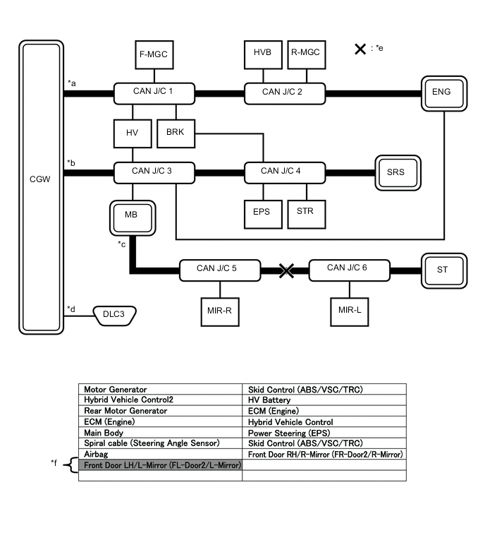
Example: Open in both CAN branch lines of MB on the bus 4
*a Background color is red *b Not displayed Tech Tips
-
In the CAN bus check, it is possible to confirm the communication status of ECUs connected to the bus after connecting the GTS to the DLC3. As for sub bus, it is possible to confirm which sub bus connected ECUs can communicate with a gateway function equipped ECU on the bus.
-
If a gateway function equipped ECU has a communication error, ECUs connected to the gateway function equipped ECU are also affected, and communication stops will be indicated.
-
The CAN Bus Check screen in the illustration shows that ECU MB has a gateway function and a communication stop in ECU MB is suspected.
-
-
If the CAN Bus Check screen indicates a communication stop only in the sub bus, a communication stop in the sub bus is suspected.
Example: Open in both CAN branch lines of MIR-R on the sub bus
*a Background color is red - - Tech Tips
-
A communication error in a sub bus does not affect the other buses.
-
When a gateway function equipped ECU has memorized the ECUs that are connected to the sub bus, if any of the ECUs connected to the gateway function equipped ECU has a communication error, the background color changes to yellow or red. (The displayed name will not disappear.)
-
-
If both of the bus 2 main bus lines are open, ECUs or sensors that are located farther away from the central gateway ECU than the open part will be displayed as a communication stop on the CAN Bus Check screen.
(In this case, HVB, R-MGC and ENG background color changes to red.)
*a Bus 2 *b Bus 4 *c Sub Bus *d V Bus *e Location of Malfunction *f Background color is red Tech Tips
If a communication error occurs in an ECU, it is not displayed on the CAN Bus Check screen even though the ECU is present.
-
If both of the sub bus main bus lines are open, ECUs that are located farther away from the gateway function equipped ECU than the open part will be displayed as a communication stop on the CAN Bus Check screen.
(In this case, MIR-L background color changes to red.)
*a Bus 2 *b Bus 4 *c Sub Bus *d V Bus *e Location of Malfunction *f Background color is red -
When any of the following malfunctions occur, CAN communication cannot be established and almost all ECUs and sensors on the bus show a communication error on the CAN Bus Check screen.
Details of Malfunction Short between CAN lines (CANH and CANL) Short between a CAN line (CANH or CANL) and +B Short between a CAN line (CANH or CANL) and ground Open in a CAN main bus line 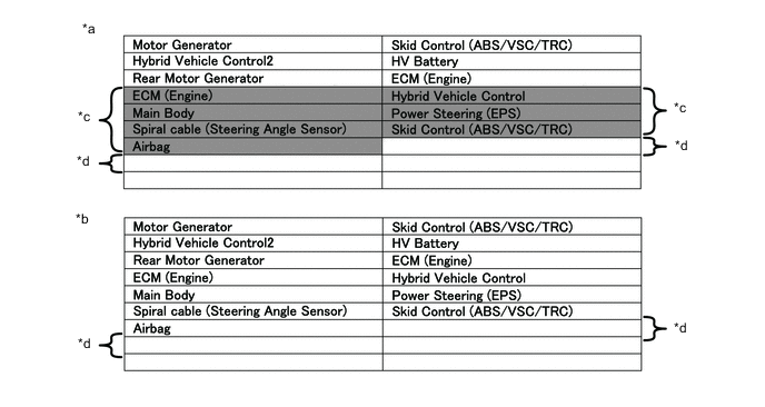
*a When any of the following malfunctions occur on the bus 4 *b When any of the following malfunctions occur on a sub bus *c Background color is red *d Not displayed Tech Tips
-
When a malfunction occurs in the bus, almost all ECUs and sensors on the bus and sub bus indicate a communication error (almost all ECUs are not displayed). As communication with the gateway function equipped ECU that is connected to the bus stops, communication from the ECUs connected to the sub bus that is monitored by the gateway function equipped ECU also stops (these ECUs are not displayed).
-
When a malfunction occurs in a sub bus, almost all ECUs connected to the sub bus indicate a communication error.
-
A communication error in a sub bus does not affect the other buses.
-
The malfunctioning part can be determined by checking for a short circuit between CAN bus lines or between a CAN bus line and ground or +B short using an electrical tester.
-
-
If a communication error of all ECUs and sensors is indicated on the CAN Bus Check screen, a communication stop of the V bus (DLC3 - central gateway ECU) is suspected.
Open in both CAN branch lines in the V bus
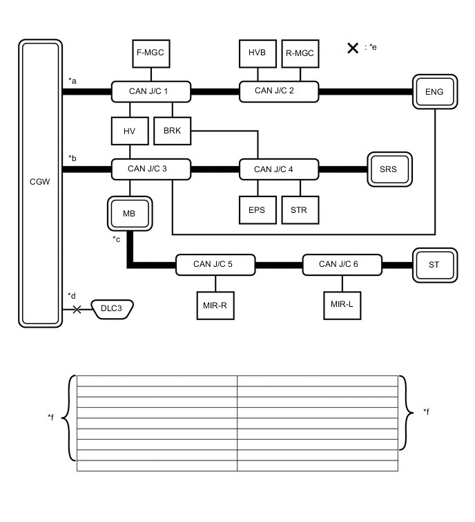
*a Bus 2 *b Bus 4 *c Sub Bus *d V Bus *e Location of Malfunction *f Not displayed Tech Tips
When there is no communication between the GTS and the vehicle, no ECUs or sensors will be displayed.
-
-
HOW TO INTERPRET COMMUNICATION DTCS (DTCS THAT START WITH U)
-
If a CAN communication error cannot be reproduced, determine the suspected malfunctioning part using the DTCs stored in ECUs that are connected to the CAN buses by following the procedure below.
Tech Tips
Communication DTCs (DTCs that start with U) indicate a communication error between the ECU that stores the DTC and the ECU that is indicated by the DTC.
-
If multiple ECUs store a communication DTC for a particular ECU, a communication stop of the ECU is suspected.
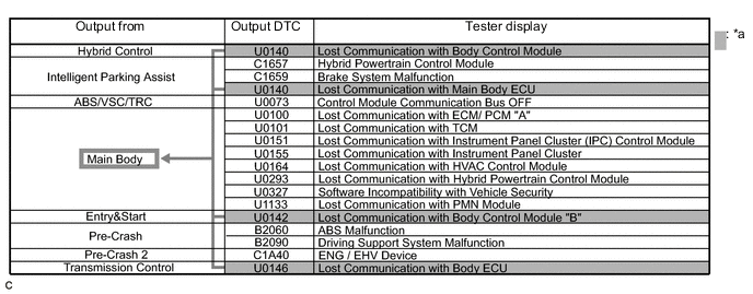
*a Items to be Checked - - Note
-
This DTC table is from another model, and is only used here to show an example of DTCs that are output when there is an open in a CAN branch line for the main body ECU. This table does not show DTCs applicable to this vehicle.
-
Even though a DTC title may indicate a communication error with a specific ECU, the ECU name used in the DTC name on the GTS may differ depending on the ECU that stores the DTC. (Regarding output DTCs, refer to the DTC chart for each ECU.)
Tech Tips
As multiple ECUs indicate a communication stop with the main body ECU, the possibility of a communication stop of the main body ECU is high.
-
-
If almost all of the communication DTCs of an ECU are stored, a communication stop of the ECU is suspected.
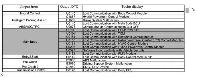
*a Items to be Checked - - Note
-
This DTC table is from another model, and is only used here to show an example of DTCs that are output when there is an open in a CAN branch line for the main body ECU. This table does not show DTCs applicable to this vehicle.
-
Even though a DTC title may indicate a communication error with a specific ECU, the ECU name used in the DTC name on the GTS may differ depending on the ECU that stores the DTC. (Regarding output DTCs, refer to DTC Table by ECU.)
Tech Tips
-
If almost all of the DTCs of the main body ECU are stored, the possibility of a communication stop of the main body ECU is high.
-
When a CAN communication error occurs, many DTCs are output. DTCs other than communication error DTCs (such as DTCs that start with C or B) and communication DTCs for the ABS system are important DTCs, however it may be easier to determine the malfunctioning part by examining the overall situation without considering these DTCs.
-
-
-
To help determine the part of the sub bus that has a communication error, prioritize the communication stop DTCs stored in the gateway function equipped ECU.
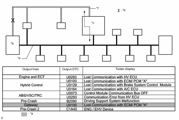
*a Items to be Checked *b ECM *c Gateway Function Equipped ECU *d Location of Malfunction *e Bus *f Sub Bus Note
This DTC table is from another model, and is only used here to show the ECUs connected to both a bus and a sub bus. It shows DTCs output when there is an open in the main bus lines for the ECM on the sub bus. This table does not show DTCs applicable to this vehicle.
Tech Tips
-
As gateway function equipped ECUs (sub bus monitor ECU) monitor signals from all ECUs that are connected to sub bus, gateway function equipped ECUs can detect ECUs with a communication stop more accurately.
-
When there is a communication stop for the gateway function equipped ECU (gateway), communication with ECUs connected to other buses such as the bus 2 stops. Therefore, communication DTCs for ECUs connected to other buses are also stored.
-
-
When any of the following malfunctions occurs, many DTCs are likely to be output from many ECUs. Because of this, it may be difficult to determine the probable malfunctioning part.
-
Short between CAN lines (CANH and CANL)
-
Short between a CAN line (CANH or CANL) and ground
-
Short between a CAN line (CANH or CANL) and +B
-
Open in a CAN branch line (CANH or CANL) of an ECU or sensor
-
Open in a CAN main bus line (CANH or CANL) between 2 ECUs that have a terminating resistor
-
-
-
DTC TABLE BY ECU
Tech Tips
-
In the CAN communication system, CAN communication system DTCs stored by the ECU can be output from the ECU by using the GTS.
-
If CAN communication system DTCs are output, the trouble cannot be determined solely from the DTCs. Perform troubleshooting according to "How to Proceed with Troubleshooting".
-
ECM
Tech Tips
DTC communication uses the CAN communication system.
DTC No. Detection Item U0129 Lost Communication with Brake System Control Module U1103*1 Lost Communication with Stop and Start Control Module
-
*1: w/ Stop and Start System
-
-
MAIN BODY ECU (MULTIPLEX NETWORK BODY ECU)
Tech Tips
DTC communication uses the CAN communication system.
DTC No. Detection Item U0100 Lost Communication with ECM/PCM "A" U0101 Lost Communication with TCM U0120 Lost Communication with Starter/Generator Control Module U0151 Lost Communication with Restraints Control Module U0155 Lost Communication with Instrument Panel Cluster (IPC) Control Module U0164 Lost Communication with HVAC Control Module U023A Lost Communication with Image Processing Module "A" U0327 Software Incompatibility with Vehicle Security Control Module -
SKID CONTROL ECU (BRAKE ACTUATOR ASSEMBLY)
Tech Tips
DTC communication uses the CAN communication system.
DTC No. Detection Item U0073 Control Module Communication Bus Off U0100 Lost Communication with ECM/PCM "A" U0124 Lost Communication with Lateral Acceleration Sensor Module U0126 Lost Communication with Steering Angle Sensor Module -
POWER STEERING ECU ASSEMBLY
Tech Tips
DTC communication uses the CAN communication system.
DTC No. Detection Item U0100 Lost Communication with ECM/PCM "A" U0129 Lost Communication with Brake System Control Module -
COMBINATION METER ASSEMBLY
Tech Tips
DTC communication uses the CAN communication system.
DTC No. Detection Item U0100 Lost Communication with ECM/PCM "A" U0129 Lost Communication with Brake System Control Module U0131 Lost Communication with Power Steering Control Module U0142 Communication with Body Control Module "B" U0151 Lost Communication with Restraints Control Module U023A Lost Communication with Front Camera Module -
RADIO AND DISPLAY RECEIVER ASSEMBLY (w/ Display)
Tech Tips
DTC communication uses the CAN communication system.
DTC No. Detection Item U0073 Control Module Communication Bus Off U0100 Lost Communication with ECM/PCM "A" U0129 Lost Communication with Brake System Control Module U0140 Lost Communication with Main Body ECU U0155 Lost Communication with Combination Meter U0164 Lost Communication with HVAC control Module -
CERTIFICATION ECU (SMART KEY ECU ASSEMBLY) (w/ Entry and Start System)
Tech Tips
DTC communication uses the CAN communication system.
DTC No. Detection Item U0100 Lost Communication with ECM/PCM "A" U0140 Lost Communication with Body Control Module U0142 Lost Communication with Body Control Module "B" U0155 Lost Communication with Instrument Panel Cluster (IPC) Control Module U1103 Lost Communication with Stop and Start Control Module -
AIR CONDITIONING AMPLIFIER ASSEMBLY (w/ Air Conditioning System or PTC Heater)
Tech Tips
DTC communication uses the CAN communication system.
DTC No. Detection Item U0100 Lost Communication with ECM/PCM "A" U0131 Lost Communication with Power Steering Control Module U0142 Lost Communication with Body Control Module "B" U0155 Lost Communication with Instrument Panel Cluster (IPC) Control Module -
ENGINE STOP AND START ECU (w/ Stop and Start System)
Tech Tips
DTC communication uses the CAN communication system.
DTC No. Detection Item U0100 Lost Communication with ECM/PCM "A" U0121 Lost Communication with Anti-Lock Brake System (ABS) Control Module U0126 Lost Communication with Steering Angle Sensor Module U0131 Lost Communication with Power Steering Control Module U0140 Lost Communication with J/B ECU U0151 Lost Communication with SRS Airbag ECU U0155 Lost Communication with Instrument Panel Cluster Control Module (Combination Meter) U0164 Lost Communication with HVAC Control Module -
PRE-CRASH SAFETY CITY SENSOR
Tech Tips
DTC communication uses the CAN communication system.
DTC No. Detection Item U0123 Lost Communication with Yaw Rate Sensor Module U0126 Lost Communication with Steering Angle Sensor Module U0129 Lost Communication with Brake System Control Module U0155 Lost Communication With Instrument Panel Cluster (IPC) Control Module U023A Lost Communication with Front Camera Module -
STEERING ANGLE SENSOR (SPIRAL CABLE SUB-ASSEMBLY)
Tech Tips
The steering angle sensor (spiral cable sub-assembly) is connected to the CAN communication system but CAN communication DTCs are not stored.
-
CENTER AIRBAG SENSOR ASSEMBLY
Tech Tips
The center airbag sensor assembly is connected to the CAN communication system but CAN communication DTCs are not stored.
-
CENTRAL GATEWAY ECU (NETWORK GATEWAY ECU)
Tech Tips
The central gateway ECU (network gateway ECU) is connected to the CAN communication system but CAN communication DTCs are not stored.
-
-
DTC COMBINATION TABLE (OPEN IN CAN BRANCH OF BUS 2, PAST COMMUNICATION ERROR)
-
Regarding the past communication error of ECUs and sensors connected to the bus 2 (in this case, normal was displayed when performing the communication bus check, but communication DTCs are output), the probable CAN branch that had a malfunction can be determined based on the following DTC combination table.
Tech Tips
-
Based on the table below and DTCs output from ECUs connected via CAN communication, the probable part for which communication stop occurred can be determined.
-
Regarding an open in a CAN branch and a communication stop that is currently occurring, the malfunctioning part can be confirmed easily by performing the communication bus check using the GTS because the ECU or sensor connected to the CAN branch does not respond (the ECU or sensor name will not be displayed on the screen).
-
If an open in a CAN main bus line, a short between the CAN bus lines (CANH and CANL) or a +B or ground short in the CAN bus occurs, DTCs of almost all ECUs (or sensors) on the CAN bus may be output, or a message indicating a communication error may be displayed on the GTS screen. In this case, check the resistance of the CAN bus (steps 9 to 15) first Click here.
-
If an open occurs in just one of the lines of a CAN branch, DTCs which are not related to malfunctioning parts may be output (DTCs may be displayed randomly), or a message indicating a communication error may be displayed.
Bus 2 (Open in one CAN branch line) Trouble Mode Output ECU Output DTC Center Airbag sensor Communication Stop Mode Click here
Air Conditioning Amplifier Communication Stop Mode Click here
Main Body ECU Communication Stop Mode Click here
Central Gateway ECU Communication Stop Mode Click here
Engine Stop and Start ECU Communication Stop Mode Click here
Bus 2 Center Airbag Sensor Assembly - - - - - - Air Conditioning Amplifier Assembly U0100 ▲ X ▲ ▲ ▲ U0131 ▲ X ▲ ▲ ▲ U0142 ▲ X X ▲ ▲ U0155 ▲ X ▲ ▲ ▲ Main Body ECU (Multiplex Network Body ECU) U0100 ▲ ▲ X ▲ ▲ U0101 ▲ ▲ X ▲ ▲ U0120 ▲ ▲ X ▲ ▲ U0151 X ▲ X ▲ ▲ U0155 ▲ ▲ X ▲ ▲ U0164 ▲ X X ▲ ▲ U023A ▲ ▲ X ▲ ▲ U0327 ▲ ▲ X ▲ ▲ Central Gateway ECU (Network Gateway ECU) - - - - - - Engine Stop and Start ECU U0100 ▲ ▲ ▲ ▲ X U0121 ▲ ▲ ▲ ▲ X U0126 ▲ ▲ ▲ ▲ X U0131 ▲ ▲ ▲ ▲ X U0140 ▲ ▲ X ▲ X U0151 X ▲ ▲ ▲ X U0155 ▲ ▲ ▲ ▲ X U0164 ▲ X ▲ ▲ X ECM U0129 ▲ ▲ ▲ ▲ ▲ U1103 ▲ ▲ ▲ ▲ X Power Steering ECU Assembly U0100 ▲ ▲ ▲ ▲ ▲ U0129 ▲ ▲ ▲ ▲ ▲ Smart Key ECU Assembly (Certification ECU) (Certification) U0100 ▲ ▲ ▲ ▲ ▲ U0155 ▲ ▲ ▲ ▲ ▲ U1103 ▲ ▲ ▲ ▲ X U0142 ▲ ▲ X ▲ ▲ Bus 2 Smart Key ECU Assembly (Certification ECU) (Push Start) U0100 ▲ ▲ ▲ ▲ ▲ U0140 ▲ ▲ X ▲ ▲ U0155 ▲ ▲ ▲ ▲ ▲ Smart Key ECU Assembly (Certification ECU) (Cranking Hold Control) U0100 ▲ ▲ ▲ ▲ ▲ Combination Meter Assembly U0100 ▲ ▲ ▲ ▲ ▲ U0129 ▲ ▲ ▲ ▲ ▲ U0131 ▲ ▲ ▲ ▲ ▲ U0142 ▲ ▲ X ▲ ▲ U0151 X ▲ ▲ ▲ ▲ U023A X ▲ ▲ ▲ ▲ Pre-crash Safety City Sensor U0100 ▲ ▲ ▲ ▲ ▲ U0123 X ▲ ▲ ▲ ▲ U0126 ▲ ▲ ▲ ▲ ▲ U0129 ▲ ▲ ▲ ▲ ▲ U0155 ▲ ▲ ▲ ▲ ▲ Spiral Cable with Sensor Sub-assembly (Steering Sensor) - - - - - - Skid Control ECU (Brake Actuator Assembly)*1 U0100 ▲ ▲ ▲ ▲ ▲ U0124 X ▲ ▲ ▲ ▲ U0126 ▲ ▲ ▲ ▲ ▲ Bus 3 Radio and Display Receiver Assembly*1 U0100 ▲ ▲ ▲ X ▲ U0129 ▲ ▲ ▲ X ▲ U0140 ▲ ▲ X X ▲ U0155 ▲ ▲ ▲ X ▲ U0164 ▲ X ▲ X ▲ Central Gateway ECU (Network Gateway ECU) - - - - - - Tech Tips
-
*1: U0073 may be stored when communication is lost.
-
X: DTC is likely to be output.
-
▲: DTC is not likely to be output.
-
-: DTC is not output.
Bus 2 (Open in one CAN branch line) Trouble Mode Output ECU Output DTC Certification ECU Communication Stop Mode Click here
Power Steering ECU Communication Stop Mode Click here
Front Camera Module Communication Stop Mode Click here
Steering Angle Sensor Communication Stop Mode Click here
ABS and Traction Actuator (Skid Control ECU) Communication Stop Mode Click here
Bus 2 Center Airbag Sensor Assembly - - - - - - Air Conditioning Amplifier Assembly U0100 ▲ ▲ ▲ ▲ ▲ U0131 ▲ ▲ ▲ ▲ ▲ U0142 ▲ ▲ ▲ ▲ ▲ U0155 ▲ ▲ ▲ ▲ ▲ Main Body ECU (Multiplex Network Body ECU) U0100 ▲ ▲ ▲ ▲ ▲ U0101 ▲ ▲ ▲ ▲ ▲ U0120 X ▲ ▲ ▲ ▲ U0151 ▲ ▲ ▲ ▲ ▲ U0155 ▲ ▲ ▲ ▲ ▲ U0164 ▲ ▲ ▲ ▲ ▲ U023A ▲ ▲ ▲ ▲ ▲ U0327 X ▲ ▲ ▲ ▲ Central Gateway ECU (Network Gateway ECU) - - - - - - Engine Stop and Start ECU U0100 ▲ ▲ ▲ ▲ ▲ U0121 ▲ ▲ ▲ ▲ X U0126 ▲ ▲ ▲ X ▲ U0131 ▲ X ▲ ▲ ▲ U0140 ▲ ▲ ▲ ▲ ▲ U0151 ▲ ▲ ▲ ▲ ▲ U0155 ▲ ▲ ▲ ▲ ▲ U0164 ▲ ▲ ▲ ▲ ▲ ECM U0129 ▲ ▲ ▲ ▲ X U1103 ▲ ▲ ▲ ▲ ▲ Power Steering ECU Assembly U0100 ▲ X ▲ ▲ ▲ U0129 ▲ X ▲ ▲ X Smart Key ECU Assembly (Certification ECU) (Certification) U0100 X ▲ ▲ ▲ ▲ U0155 X ▲ ▲ ▲ ▲ U1103 X ▲ ▲ ▲ ▲ U0142 X ▲ ▲ ▲ ▲ Bus 2 Smart Key ECU Assembly (Certification ECU) (Push Start) U0100 X ▲ ▲ ▲ ▲ U0140 X ▲ ▲ ▲ ▲ U0155 X ▲ ▲ ▲ ▲ Smart Key ECU Assembly (Certification ECU) (Cranking Hold Control) U0100 X ▲ ▲ ▲ ▲ Combination Meter Assembly U0100 ▲ ▲ ▲ ▲ ▲ U0129 ▲ ▲ ▲ ▲ X U0131 ▲ X ▲ ▲ ▲ U0142 ▲ ▲ ▲ ▲ ▲ U0151 ▲ ▲ ▲ ▲ ▲ U023A ▲ ▲ ▲ ▲ ▲ Pre-crash Safety City Sensor U0100 ▲ ▲ X ▲ ▲ U0123 ▲ ▲ X ▲ ▲ U0126 ▲ ▲ X X ▲ U0129 ▲ ▲ X ▲ X U0155 ▲ ▲ X ▲ ▲ Spiral Cable with Sensor Sub-assembly (Steering Sensor) - - - - - - Skid Control ECU (Brake Actuator Assembly)*1 U0100 ▲ ▲ ▲ ▲ X U0124 ▲ ▲ ▲ ▲ X U0126 ▲ ▲ ▲ X X Bus 3 Radio and Display Receiver Assembly*1 U0100 ▲ ▲ ▲ ▲ ▲ U0129 ▲ ▲ ▲ ▲ X U0140 ▲ ▲ ▲ ▲ ▲ U0155 ▲ ▲ ▲ ▲ ▲ U0164 ▲ ▲ ▲ ▲ ▲ Central Gateway ECU (Network Gateway ECU) - - - - - - Tech Tips
-
*1: U0073 may be stored when communication is lost.
-
X: DTC is likely to be output.
-
▲: DTC is not likely to be output.
-
-: DTC is not output.
Bus 2 (Open in Both CAN branch line) Trouble Mode Output ECU Output DTC Center Airbag sensor Communication Stop Mode Click here
Air Conditioning Amplifier Communication Stop Mode Click here
Main Body ECU Communication Stop Mode Click here
Central Gateway ECU Communication Stop Mode Click here
Engine Stop and Start ECU Communication Stop Mode Click here
Bus 2 Center Airbag Sensor Assembly - - - - - - Air Conditioning Amplifier Assembly U0100 - ○ - - - U0131 - ○ - - - U0142 - ○ ○ - - U0155 - ○ - - - Main Body ECU (Multiplex Network Body ECU) U0100 - - ○ - - U0101 - - ○ - - U0120 - - ○ - - U0151 ○ - ○ - - U0155 - - ○ - - U0164 - ○ ○ - - U023A - - ○ - - U0327 - - ○ - - Central Gateway ECU (Network Gateway ECU) - - - - - - Engine Stop and Start ECU U0100 - - - - ○ U0121 - - - - ○ U0126 - - - - ○ U0131 - - - - ○ U0140 - - ○ - ○ U0151 ○ - - - ○ U0155 - - - - ○ U0164 - ○ - - ○ ECM U0129 - - - - - U1103 - - - - ○ Power Steering ECU Assembly U0100 - - - - - U0129 - - - - - Smart Key ECU Assembly (Certification ECU) (Certification) U0100 - - - - - U0155 - - - - - U1103 - - - - ○ U0142 - - ○ -- - Bus 2 Smart Key ECU Assembly (Certification ECU) (Push Start) U0100 - - - - - U0140 - - ○ - - U0155 - - - - - Smart Key ECU Assembly (Certification ECU) (Cranking Hold Control) U0100 - - - - - Combination Meter Assembly U0100 - - - - - U0129 - - - - - U0131 - - - - - U0142 - - ○ - - U0151 ○ - - - - U023A ○ - - - - Pre-crash Safety City Sensor U0100 - - - - - U0123 ○ - - - - U0126 - - - - - U0129 - - - - - U0155 - - - - - Spiral Cable with Sensor Sub-assembly (Steering Sensor) - - - - - - Skid Control ECU (Brake Actuator Assembly)*1 U0100 - - - - - U0124 ○ - - - - U0126 - - - - - Bus 3 Radio and Display Receiver Assembly*1 U0100 - - - ○ - U0129 - - - ○ - U0140 - - ○ ○ - U0155 - - - ○ - U0164 - ○ - ○ - Central Gateway ECU (Network Gateway ECU) - - - - - - Tech Tips
-
*1: U0073 may be stored when communication is lost.
-
○ : DTC is output.
-
-: DTC is not output.
Bus 2 (Open in Both CAN branch line) Trouble Mode Output ECU Output DTC Certification ECU Communication Stop Mode Click here
Power Steering ECU Communication Stop Mode Click here
Front Camera Module Communication Stop Mode Click here
Steering Angle Sensor Communication Stop Mode Click here
ABS and Traction Actuator (Skid Control ECU) Communication Stop Mode Click here
Bus 2 Center Airbag Sensor Assembly - - - - - - Air Conditioning Amplifier Assembly U0100 - - - - - U0131 - - - - - U0142 - - - - - U0155 - - - - - Main Body ECU (Multiplex Network Body ECU) U0100 - - - - - U0101 - - - - - U0120 ○ - - - - U0151 - - - - - U0155 - - - - - U0164 - - - - - U023A - - - - - U0327 ○ - - - - Central Gateway ECU (Network Gateway ECU) - - - - - - Engine Stop and Start ECU U0100 - - - - - U0121 - - - - ○ U0126 - - - ○ - U0131 - ○ - - - U0140 - - - - - U0151 - - - - - U0155 - - - - - U0164 - - - - - ECM U0129 - - - - ○ U1103 - - - - - Power Steering ECU Assembly U0100 - ○ - - - U0129 - ○ - - ○ Smart Key ECU Assembly (Certification ECU) (Certification) U0100 ○ - - - - U0155 ○ - - - - U1103 ○ - - - - U0142 ○ - - - - Bus 2 Smart Key ECU Assembly (Certification ECU) (Push Start) U0100 ○ - - - - U0140 ○ - - - - U0155 ○ - - - - Smart Key ECU Assembly (Certification ECU) (Cranking Hold Control) U0100 ○ - - - - Combination Meter Assembly U0100 - - - - - U0129 - - - - ○ U0131 - ○ - - - U0142 - - - - - U0151 - - - - - U023A - - - - - Pre-crash Safety City Sensor U0100 - - ○ - - U0123 - - ○ - - U0126 - - ○ ○ - U0129 - - ○ - ○ U0155 - - ○ - - Spiral Cable with Sensor Sub-assembly (Steering Sensor) - - - - - - Skid Control ECU (Brake Actuator Assembly)*1 U0100 - - - - ○ U0124 - - - - ○ U0126 - - - ○ ○ Bus 3 Radio and Display Receiver Assembly*1 U0100 - - - - - U0129 - - - - ○ U0140 - - - - - U0155 - - - - - U0164 - - - - - Central Gateway ECU (Network Gateway ECU) - - - - - - Tech Tips
-
*1: U0073 may be stored when communication is lost.
-
○ : DTC is output.
-
-: DTC is not output.
Bus 2 (Open in one CAN main line) Bus 2 (Open in Both CAN main line) Trouble Mode Trouble Mode Output ECU Output DTC Combination Meter ECU Communication Stop Mode Click here
No. 1 CAN J/C to No. 2 CAN J/C ECM Communication Stop Mode Click here
Combination Meter ECU Communication Stop Mode Click here
No. 1 CAN J/C to No. 2 CAN J/C ECM Communication Stop Mode Click here
Bus 2 Center Airbag Sensor Assembly - - - - - - - Air Conditioning Amplifier Assembly U0100 X X X ○ ○ ○ U0131 ▲ ▲ ▲ - - - U0142 ▲ X ▲ - ○ - U0155 X ▲ ▲ ○ - - Main Body ECU (Multiplex Network Body ECU) U0100 ▲ ▲ X - - ○ U0101 ▲ ▲ X - - ○ U0120 ▲ X ▲ - ○ - U0151 ▲ X ▲ - ○ - U0155 X X ▲ ○ ○ - U0164 ▲ X ▲ - ○ - U023A ▲ ▲ ▲ - - - U0327 ▲ X ▲ - ○ - Central Gateway ECU (Network Gateway ECU) - - - - - - - Engine Stop and Start ECU U0100 ▲ ▲ X - - ○ U0121 ▲ ▲ ▲ - - - U0126 ▲ X ▲ - ○ - U0131 ▲ X ▲ - ○ - U0140 ▲ ▲ ▲ - - - U0151 ▲ X ▲ - ○ - U0155 ▲ X ▲ - ○ - U0164 ▲ X ▲ - ○ - ECM U0129 ▲ ▲ X - - ○ U1103 ▲ ▲ X - - ○ Power Steering ECU Assembly U0100 ▲ X X - ○ ○ U0129 ▲ X ▲ - ○ - Smart Key ECU Assembly (Certification ECU) (Certification) U0100 ▲ X X - ○ ○ U0155 X ▲ ▲ ○ - - U1103 ▲ X ▲ - ○ - U0142 ▲ X ▲ - ○ - Bus 2 Smart Key ECU Assembly (Certification ECU) (Push Start) U0100 ▲ X X - ○ ○ U0140 ▲ X ▲ - ○ - U0155 X ▲ ▲ ○ - - Smart Key ECU Assembly (Certification ECU) (Cranking Hold Control) U0100 ▲ X X - ○ ○ Combination Meter Assembly U0100 X X X ○ ○ ○ U0129 X X ▲ ○ ○ - U0131 X ▲ ▲ ○ - - U0142 X X ▲ ○ ○ - U0151 X ▲ ▲ ○ - - U023A X X ▲ ○ ○ - Pre-crash Safety City Sensor U0100 ▲ ▲ X - - ○ U0123 ▲ X ▲ - ○ - U0126 ▲ X ▲ - ○ - U0129 ▲ ▲ ▲ - - - U0155 X X ▲ ○ ○ - Spiral Cable with Sensor Sub-assembly (Steering Sensor) - - - - - - - Skid Control ECU (Brake Actuator Assembly)*1 U0100 ▲ ▲ X - - ○ U0124 ▲ X ▲ - ○ - U0126 ▲ X ▲ - ○ - Bus 3 Radio and Display Receiver Assembly*1 U0100 ▲ X X - ○ ○ U0129 ▲ X ▲ - ○ - U0140 ▲ X ▲ - ○ - U0155 X ▲ ▲ ○ - - U0164 ▲ ▲ ▲ - - - Central Gateway ECU (Network Gateway ECU) - - - - - - - Tech Tips
-
*1: U0073 may be stored when communication is lost.
-
X: DTC is likely to be output.
-
▲: DTC is not likely to be output.
-
-: DTC is not output.
Bus 2 (CAN bus line short circuit) Bus 2 (CAN bus line short to GND) Trouble Mode Trouble Mode Output ECU Output DTC CANH to CANL CANH to GND CANL to GND Bus 2 Center Airbag Sensor Assembly - - - - Air Conditioning Amplifier Assembly U0100 ○ ○ ○ U0131 ○ ○ ○ U0142 ○ ○ ○ U0155 ○ ○ ○ Main Body ECU (Multiplex Network Body ECU) U0100 ○ ○ ○ U0101 ○ ○ ○ U0120 ○ ○ ○ U0151 ○ ○ ○ U0155 ○ ○ ○ U0164 ○ ○ ○ U023A ○ ○ ○ U0327 ○ ○ ○ Central Gateway ECU (Network Gateway ECU) - - - - Engine Stop and Start ECU U0100 ○ ○ ○ U0121 ○ ○ ○ U0126 ○ ○ ○ U0131 ○ ○ ○ U0140 ○ ○ ○ U0151 ○ ○ ○ U0155 ○ ○ ○ U0164 ○ ○ ○ ECM U0129 ○ ○ ○ U1103 ○ ○ ○ Power Steering ECU Assembly U0100 ○ ○ ○ U0129 ○ ○ ○ Smart Key ECU Assembly (Certification ECU) (Certification) U0100 ○ ○ ○ U0155 ○ ○ ○ U1103 ○ ○ ○ U0142 ○ ○ ○ Smart Key ECU Assembly (Certification ECU) (Push Start) U0100 ○ ○ ○ U0140 ○ ○ ○ U0155 ○ ○ ○ Bus 2 Smart Key ECU Assembly (Certification ECU) (Cranking Hold Control) U0100 ○ ○ ○ Combination Meter Assembly U0100 ○ ○ ○ U0129 ○ ○ ○ U0131 ○ ○ ○ U0142 ○ ○ ○ U0151 ○ ○ ○ U023A ○ ○ ○ Pre-crash Safety City Sensor U0100 ○ ○ ○ U0123 ○ ○ ○ U0126 ○ ○ ○ U0129 ○ ○ ○ U0155 ○ ○ ○ Spiral Cable with Sensor Sub-assembly (Steering Sensor) - - - - Skid Control ECU (Brake Actuator Assembly)*1 U0100 ○ ○ ○ U0124 ○ ○ ○ U0126 ○ ○ ○ Bus 3 Radio and Display Receiver Assembly*1 U0100 ○ ○ ○ U0129 ○ ○ ○ U0140 ○ ○ ○ U0155 ○ ○ ○ U0164 ○ ○ ○ Central Gateway ECU (Network Gateway ECU) - - - - Tech Tips
-
*1: U0073 may be stored when communication is lost.
-
○ : DTC is output.
-
-: DTC is not output.
-
-
-
DTC COMBINATION TABLE (OPEN IN CAN BRANCH OF BUS 3, PAST COMMUNICATION ERROR)
-
Regarding the past communication error of ECUs and sensors connected to the bus 3 (in this case, normal was displayed when performing the communication bus check, but communication DTCs are output), the probable CAN branch that had a malfunction can be determined based on the following DTC combination table.
Tech Tips
-
Based on the table below and DTCs output from ECUs connected via CAN communication, the probable part for which communication stop occurred can be determined.
-
Regarding an open in a CAN branch and a communication stop that is currently occurring, the malfunctioning part can be confirmed easily by performing the communication bus check using the GTS because the ECU or sensor connected to the CAN branch does not respond (the ECU or sensor name will not be displayed on the screen).
-
If an open in a CAN main bus line, a short between the CAN bus lines (CANH and CANL) or a +B or ground short in the CAN bus occurs, DTCs of almost all ECUs (or sensors) on the CAN bus may be output, or a message indicating a communication error may be displayed on the GTS screen. In this case, check the resistance of the CAN bus (steps 9 to 15) first Click here.
-
If an open occurs in just one of the lines of a CAN branch, DTCs which are not related to malfunctioning parts may be output (DTCs may be displayed randomly), or a message indicating a communication error may be displayed.
Bus 3 (Open in one CAN branch line) Trouble Mode Output ECU Output DTC Audio Receiver Assembly Communication Stop Mode Click here
Bus 2 Center Airbag Sensor Assembly - - Air Conditioning Amplifier Assembly U0100 - U0131 - U0142 - U0155 - Main Body ECU (Multiplex Network Body ECU) U0100 - U0101 - U0120 - U0151 - U0155 - U0164 - U023A - U0327 - Central Gateway ECU (Network Gateway ECU) - - Engine Stop and Start ECU U0100 - U0121 - U0126 - U0131 - U0140 - U0151 - U0155 - U0164 - ECM U0129 - U1103 - Power Steering ECU Assembly U0100 - U0129 - Smart Key ECU Assembly (Certification ECU) (Certification) U0100 - U0155 - U1103 - U0142 - Smart Key ECU Assembly (Certification ECU) (Push Start) U0100 - U0140 - U0155 - Smart Key ECU Assembly (Certification ECU) (Cranking Hold Control) U0100 - Bus 2 Combination Meter Assembly U0100 - U0129 - U0131 - U0142 - U0151 - U023A - Pre-crash Safety City Sensor U0100 - U0123 - U0126 - U0129 - U0155 - Spiral Cable with Sensor Sub-assembly (Steering Sensor) - - Skid Control ECU (Brake Actuator Assembly)*1 U0100 - U0124 - U0126 - Bus 3 Radio and Display Receiver Assembly*1 U0100 X U0129 X U0140 X U0155 X U0164 X Central Gateway ECU (Network Gateway ECU) - X Tech Tips
-
*1: U0073 may be stored when communication is lost.
-
X: DTC is likely to be output.
-
▲: DTC is not likely to be output.
-
-: DTC is not output.
Bus 3 (Open in Both CAN branch line) Trouble Mode Output ECU Output DTC Audio Receiver Assembly Communication Stop Mode Click here
Bus 2 Center Airbag Sensor Assembly - - Air Conditioning Amplifier Assembly U0100 - U0131 - U0142 - U0155 - Main Body ECU (Multiplex Network Body ECU) U0100 - U0101 - U0120 - U0151 - U0155 - U0164 - U023A - U0327 - Central Gateway ECU (Network Gateway ECU) - - Engine Stop and Start ECU U0100 - U0121 - U0126 - U0131 - U0140 - U0151 - U0155 - U0164 - ECM U0129 - U1103 - Power Steering ECU Assembly U0100 - U0129 - Smart Key ECU Assembly (Certification ECU) (Certification) U0100 - U0155 - U1103 - U0142 - Smart Key ECU Assembly (Certification ECU) (Push Start) U0100 - U0140 - U0155 - Smart Key ECU Assembly (Certification ECU) (Cranking Hold Control) U0100 - Bus 2 Combination Meter Assembly U0100 - U0129 - U0131 - U0142 - U0151 - U023A - Pre-crash Safety City Sensor U0100 - U0123 - U0126 - U0129 - U0155 - Spiral Cable with Sensor Sub-assembly (Steering Sensor) - - Skid Control ECU (Brake Actuator Assembly)*1 U0100 - U0124 - U0126 - Bus 3 Radio and Display Receiver Assembly*1 U0100 ○ U0129 ○ U0140 ○ U0155 ○ U0164 ○ Central Gateway ECU (Network Gateway ECU) - ○ Tech Tips
-
*1: U0073 may be stored when communication is lost.
-
○ : DTC is output.
-
-: DTC is not output.
Bus 3 (Open in one CAN main line) Bus 3 (Open in Both CAN main line) Trouble Mode Trouble Mode Output ECU Output DTC Central Gateway ECU (CA3H and CA3L Terminal) Central Gateway ECU (CAYH and CAYL Terminal) Central Gateway ECU (CA3H and CA3L Terminal) Central Gateway ECU (CAYH and CAYL Terminal) Bus 2 Center Airbag Sensor Assembly - - - - - Air Conditioning Amplifier Assembly U0100 - - - - U0131 - - - - U0142 - - - - U0155 - - - - Main Body ECU (Multiplex Network Body ECU) U0100 - - - - U0101 - - - - U0120 - - - - U0151 - - - - U0155 - - - - U0164 - - - - U023A - - - - U0327 - - - - Central Gateway ECU (Network Gateway ECU) - - - - - Engine Stop and Start ECU U0100 - - - - U0121 - - - - U0126 - - - - U0131 - - - - U0140 - - - - U0151 - - - - U0155 - - - - U0164 - - - - ECM U0129 - - - - U1103 - - - - Power Steering ECU Assembly U0100 - - - - U0129 - - - - Smart Key ECU Assembly (Certification ECU) (Certification) U0100 - - - - U0155 - - - - U1103 - - - - U0142 - - - - Smart Key ECU Assembly (Certification ECU) (Push Start) U0100 - - - - U0140 - - - - U0155 - - - - Smart Key ECU Assembly (Certification ECU) (Cranking Hold Control) U0100 - - - - Bus 2 Combination Meter Assembly U0100 - - - - U0129 - - - - U0131 - - - - U0142 - - - - U0151 - - - - U023A - - - - Pre-crash Safety City Sensor U0100 - - - - U0123 - - - - U0126 - - - - U0129 - - - - U0155 - - - - Spiral Cable with Sensor Sub-assembly (Steering Sensor) - - - - - Skid Control ECU (Brake Actuator Assembly)*1 U0100 - - - - U0124 - - - - U0126 - - - - Bus 3 Radio and Display Receiver Assembly*1 U0100 X ▲ ○ - U0129 X ▲ ○ - U0140 X ▲ ○ - U0155 X ▲ ○ - U0164 X ▲ ○ - Central Gateway ECU (Network Gateway ECU) - - - - - Tech Tips
-
*1: U0073 may be stored when communication is lost.
-
X: DTC is likely to be output.
-
▲: DTC is not likely to be output.
-
-: DTC is not output.
Bus 3 (CAN bus line short circuit) Bus 3 (CAN bus line short to GND) Trouble Mode Trouble Mode Output ECU Output DTC CANH to CANL CANH to GND CANL to GND Bus 2 Center Airbag Sensor Assembly - - - - Air Conditioning Amplifier Assembly U0100 - - - U0131 - - - U0142 - - - U0155 - - - Main Body ECU (Multiplex Network Body ECU) U0100 - - - U0101 - - - U0120 - - - U0151 - - - U0155 - - - U0164 - - - U023A - - - U0327 - - - Central Gateway ECU (Network Gateway ECU) - - - - Engine Stop and Start ECU U0100 - - - U0121 - - - U0126 - - - U0131 - - - U0140 - - - U0151 - - - U0155 - - - U0164 - - - ECM U0129 - - - U1103 - - - Power Steering ECU Assembly U0100 - - - U0129 - - - Smart Key ECU Assembly (Certification ECU) (Certification) U0100 - - - U0155 - - - U1103 - - - U0142 - - - Smart Key ECU Assembly (Certification ECU) (Push Start) U0100 - - - U0140 - - - U0155 - - - Smart Key ECU Assembly (Certification ECU) (Cranking Hold Control) U0100 - - - Bus 2 Combination Meter Assembly U0100 - - - U0129 - - - U0131 - - - U0142 - - - U0151 - - - U023A - - - Pre-crash Safety City Sensor U0100 - - - U0123 - - - U0126 - - - U0129 - - - U0155 - - - Spiral Cable with Sensor Sub-assembly (Steering Sensor) - - - - Skid Control ECU (Brake Actuator Assembly)*1 U0100 - - - U0124 - - - U0126 - - - Bus 3 Radio and Display Receiver Assembly*1 U0100 ○ ○ ○ U0129 ○ ○ ○ U0140 ○ ○ ○ U0155 ○ ○ ○ U0164 ○ ○ ○ Central Gateway ECU (Network Gateway ECU) - - - - Tech Tips
-
*1: U0073 may be stored when communication is lost.
-
○ : DTC is output.
-
-: DTC is not output.
-
-