CAN COMMUNICATION SYSTEM(w/ Toyota Safety Sense) TERMINALS OF ECU
Tech Tips
Operating the ignition switch, any switches or any doors triggers related ECU and sensor communication with the CAN, which causes resistance variation.
-
DISCONNECT CABLE FROM NEGATIVE BATTERY TERMINAL
-
Disconnect the cable from the negative (-) battery terminal before measuring the resistances of the main wire and branch wire.
CAUTION:
Wait at least 90 seconds after disconnecting the cable from the negative (-) battery terminal to disable the SRS system.
Note
-
Before measuring the resistance, leave the vehicle for at least 1 minute and do not operate the ignition switch, any switches or any doors. If doors need to be opened in order to check connectors, open the doors and leave them open.
-
When disconnecting the cable, some systems need to be initialized after the cable is reconnected Click here.
-
-
NO. 1 JUNCTION CONNECTOR
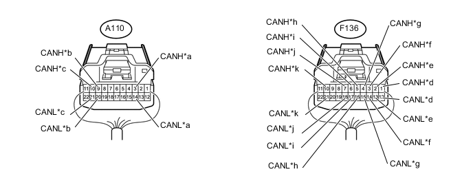
Text in Illustration *a to ECM (Sub Bus 15)*1 *b to ECM (Bus 2) *c to Skid Control ECU (Brake Actuator Assembly) (Bus 2) *d to Main Body ECU (Multiplex Network Body ECU) (Bus 2) *e to Pre-crash Safety City Sensor (for Bus 2) *f to Engine Stop and Start ECU (Bus 2)*2 *g to No. 2 Junction Connector (Bus 2) *h to Radio and Display Receiver Assembly (for Bus 3)*3 *i to Central Gateway ECU (Network Gateway ECU) (CAYH and CAYL Terminal) (for Bus 3) *j to Central Gateway ECU (Network Gateway ECU) (CA3H and CA3L Terminal) (for Bus 3) *k to Power Management Control ECU (Sub Bus 15)*1 - - Terminal No. (Symbol) Wiring Color Connect to A110-3 (CANH) B ECM (Sub Bus 15)*1 A110-14 (CANL) W A110-9 (CANH) L ECM (Bus 2) A110-20 (CANL) W A110-10 (CANH) G Skid Control ECU (Brake Actuator Assembly) (Bus 2) A110-21 (CANL) W F136-1 (CANH) R Main Body ECU (Multiplex Network Body ECU) (Bus 2) F136-12 (CANL) W F136-2 (CANH) R Pre-crash Safety City Sensor (for Bus 2) F136-13 (CANL) W F136-3 (CANH) BE Engine Stop and Start ECU (for Bus 2)*2 F136-14 (CANL) W F136-4 (CANH) SB No. 2 Junction Connector (Bus 2) F136-15 (CANL) W F136-5 (CANH) BE Radio and Display Receiver Assembly (for Bus 3)*3 F136-16 (CANL) W F136-6 (CANH) R Central Gateway ECU (Network Gateway ECU) (CAYH and CAYL Terminal) (for Bus 3) F136-17 (CANL) W F136-7 (CANH) G Central Gateway ECU (Network Gateway ECU) (CA3H and CA3L Terminal) (for Bus 3) F136-18 (CANL) W F136-10 (CANH) Y Power Management Control ECU (Sub Bus 15)*1 F136-21 (CANL) W
-
*1: for 1NR-FE
-
*2: w/ Stop and Start System
-
*3: w/ Display
-
-
NO. 2 JUNCTION CONNECTOR
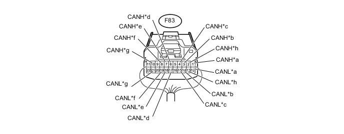
Text in Illustration *a to Steering Angle Sensor (Spiral Cable Sub-assembly) (Bus 2) *b to Certification ECU (Smart Key ECU) (Bus 2)*1 *c to Center Airbag Sensor Assembly (Bus 2) *d to Power Steering ECU Assembly (Bus 2) *e to Combination Meter Assembly (Bus 2) *f to Air Conditioning Amplifier Assembly (Bus 2)*2 *g to No. 1 Junction Connector (Bus 2) *h to Central Gateway ECU (Network Gateway ECU) (for Bus 2) Terminal No. (Symbol) Wiring Color Connect to F83-1 (CANH) P Steering Angle Sensor (Spiral Cable Sub-assembly) (Bus 2) F83-12 (CANL) W F83-2 (CANH) L Central Gateway ECU (Network Gateway ECU) (for Bus 2) F83-13 (CANL) W F83-3 (CANH) L Certification ECU (Smart Key ECU) (Bus 2)*1 F83-14 (CANL) W F83-4 (CANH) B Center Airbag Sensor Assembly (Bus 2) F83-15 (CANL) W F83-6 (CANH) LG Power Steering ECU Assembly (Bus 2) F83-17 (CANL) W F83-7 (CANH) G Combination Meter Assembly (Bus 2) F83-18 (CANL) W F83-8 (CANH) V Air Conditioning Amplifier Assembly (Bus 2)*2 F83-19 (CANL) W F83-10 (CANH) SB No. 1 Junction Connector (Bus 2) F83-21 (CANL) W
-
*1: w/ Entry and Start System
-
*2: w/ Air Conditioning System
-
-
-
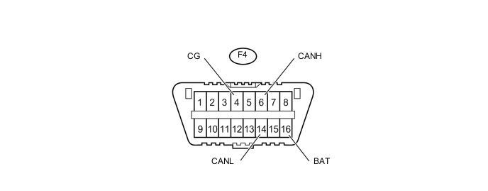
CHECK DLC3
-
Turn the ignition switch off.
-
Measure the resistance according to the value(s) in the table below.
for Bus 2 Terminal No. (Symbol) Wiring Color Switch Condition Specified Condition F4-6 (CANH) - F4-14 (CANL) GR - W Ignition switch off 54 to 66 Ω F4-6 (CANH) - F4-16 (BAT) GR - BE Ignition switch off 6 kΩ or higher F4-14 (CANL) - F4-16 (BAT) W - BE Ignition switch off 6 kΩ or higher F4-6 (CANH) - F4-4 (CG) GR - W-B Ignition switch off 200 Ω or higher F4-14 (CANL) - F4-4 (CG) W - W-B Ignition switch off 200 Ω or higher
-
-
CENTRAL GATEWAY ECU (NETWORK GATEWAY ECU)
-
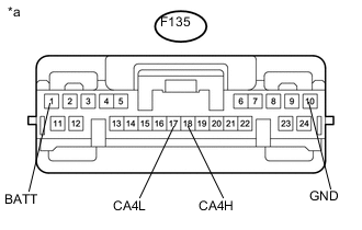
Text in Illustration *a Front view of wire harness connector
(to Central Gateway ECU (Network Gateway ECU))
Disconnect the central gateway ECU (network gateway ECU) connector.
-
Measure the resistance according to the value(s) in the table below.
for Bus 2 Terminal No. (Symbol) Wiring Color Switch Condition Specified Condition F135-18 (CA4H) - F135-17 (CA4L) L - W Ignition switch off 54 to 69 Ω F135-18 (CA4H) - F135-10 (GND) L - W-B Ignition switch off 200 Ω or higher F135-17 (CA4L) - F135-10 (GND) W - W-B Ignition switch off 200 Ω or higher F135-18 (CA4H) - F135-1 (BATT) L - BE Ignition switch off 6 kΩ or higher F135-17 (CA4L) - F135-1 (BATT) W - BE Ignition switch off 6 kΩ or higher -
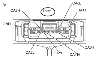
Text in Illustration *a Rear view of wire harness connector
(to Central Gateway ECU (Network Gateway ECU))
Reconnect the central gateway ECU (network gateway ECU) connector.
-
Measure the resistance according to the value(s) in the table below.
for V Bus Terminal No. (Symbol) Wiring Color Switch Condition Specified Condition F135-14 (CA6H) - F135-5 (CA6L) GR - W Ignition switch off 54 to 66 Ω F135-14 (CA6H) - F135-10 (GND) GR - W-B Ignition switch off 200 Ω or higher F135-5 (CA6L) - F135-10 (GND) W - W-B Ignition switch off 200 Ω or higher F135-14 (CA6H) - F135-1 (BATT) GR - BE Ignition switch off 6 kΩ or higher F135-5 (CA6L) - F135-1 (BATT) W - BE Ignition switch off 6 kΩ or higher for Bus 3 Terminal No. (Symbol) Wiring Color Switch Condition Specified Condition F135-6 (CA3H) - F135-21 (CA3L) G - W Ignition switch off 54 to 69 Ω F135-6 (CA3H) - F135-10 (GND) G - W-B Ignition switch off 200 Ω or higher F135-21 (CA3L) - F135-10 (GND) W - W-B Ignition switch off 200 Ω or higher F135-6 (CA3H) - F135-1 (BATT) G - BE Ignition switch off 6 kΩ or higher F135-21 (CA3L) - F135-1 (BATT) W - BE Ignition switch off 6 kΩ or higher F135-19 (CAYH) - F135-20 (CAYL) R - W Ignition switch off 54 to 69 Ω F135-19 (CAYH) - F135-10 (GND) R - W-B Ignition switch off 200 Ω or higher F135-20 (CAYL) - F135-10 (GND) W - W-B Ignition switch off 200 Ω or higher F135-19 (CAYH) - F135-1 (BATT) R - BE Ignition switch off 6 kΩ or higher F135-20 (CAYL) - F135-1 (BATT) W - BE Ignition switch off 6 kΩ or higher
-
-
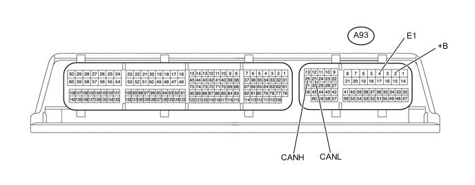
CHECK ECM (for 1KR-FE)
-
Disconnect the A93 ECM connector.
-
Measure the resistance according to the value(s) in the table below.
for Bus 2 Terminal No. (Symbol) Wiring Color Switch Condition Specified Condition A93-26 (CANH) - A93-25 (CANL) L - W Ignition switch off 108 to 132 Ω A93-26 (CANH) - A93-2 (+B) L - B Ignition switch off 6 kΩ or higher A93-25 (CANL) - A93-2 (+B) W - B Ignition switch off 6 kΩ or higher A93-26 (CANH) - A93-4 (E1) L - W-B Ignition switch off 200 Ω or higher A93-25 (CANL) - A93-4 (E1) W - W-B Ignition switch off 200 Ω or higher
-
-
CHECK ECM (for 1NR-FE)
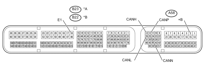
Text in Illustration *A for RHD *B for LHD
-
Disconnect the A58 ECM and B23*1 or B22*2 ECM connectors.
-
Measure the resistance according to the value(s) in the table below.
for Bus 2 Terminal No. (Symbol) Wiring Color Switch Condition Specified Condition A58-13 (CANH) - A58-26 (CANL) L - W Ignition switch off 108 to 132 Ω A58-13 (CANH) - A58-2 (+B) L - B Ignition switch off 6 kΩ or higher A58-26 (CANL) - A58-2 (+B) W - B Ignition switch off 6 kΩ or higher A58-13 (CANH) - B23-16 (E1)*1
A58-13 (CANH) - B22-16 (E1)*2
L - W-B Ignition switch off 200 Ω or higher A58-26 (CANL) - B23-16 (E1)*1
A58-26 (CANL) - B22-16 (E1)*2
W - W-B Ignition switch off 200 Ω or higher for Sub Bus 15 Terminal No. (Symbol) Wiring Color Switch Condition Specified Condition A58-12 (CANP) - A58-25 (CANN) B - W Ignition switch off 108 to 132 Ω A58-12 (CANP) - A58-2 (+B) B - B Ignition switch off 6 kΩ or higher A58-25 (CANN) - A58-2 (+B) W - B Ignition switch off 6 kΩ or higher A58-12 (CANP) - B23-16 (E1)*1
A58-12 (CANP) - B22-16 (E1)*2
B - W-B Ignition switch off 200 Ω or higher A58-25 (CANN) - B23-16 (E1)*1
A58-25 (CANN) - B22-16 (E1)*2
W - W-B Ignition switch off 200 Ω or higher
*1: for RHD
*2: for LHD
-
-
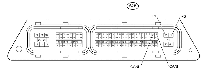
CHECK ECM (for 1ND-TV without DPF)
-
Disconnect the A59 ECM connector.
-
Measure the resistance according to the value(s) in the table below.
for Bus 2 Terminal No. (Symbol) Wiring Color Switch Condition Specified Condition A59-3 (CANH) - A59-4 (CANL) L - W Ignition switch off 108 to 132 Ω A59-3 (CANH) - A59-1 (+B) L - B Ignition switch off 6 kΩ or higher A59-4(CANL) - A59-1 (+B) W - B Ignition switch off 6 kΩ or higher A59-3 (CANH) - A59-2 (E1) L - W-B Ignition switch off 200 Ω or higher A59-4 (CANL) - A59-2 (E1) W - W-B Ignition switch off 200 Ω or higher
-
-
CHECK ECM (for 1ND-TV with DPF)
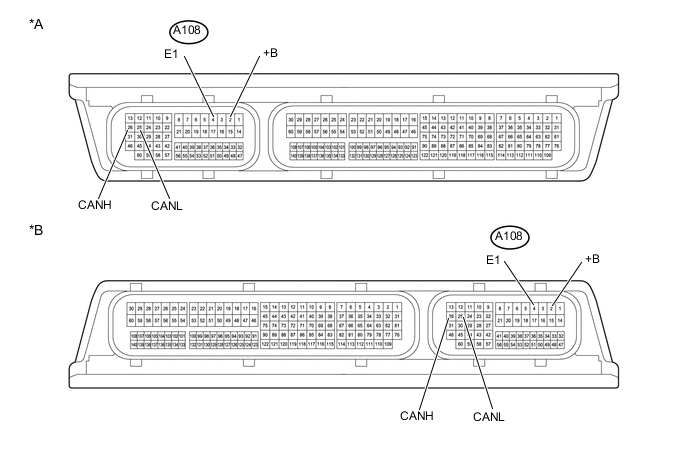
Text in Illustration *A for RHD *B for LHD
-
Disconnect the A108 ECM connector.
-
Measure the resistance according to the value(s) in the table below.
for Bus 2 Terminal No. (Symbol) Wiring color Switch Condition Specified Condition A108-26 (CANH) - A108-25 (CANL) L - W Ignition switch off 108 to 132 Ω A108-26 (CANH) - A108-2 (+B) L - B Ignition switch off 6 kΩ or higher A108-25 (CANL) - A108-2 (+B) W - B Ignition switch off 6 kΩ or higher A108-26 (CANH) - A108-4 (E1) L - W-B Ignition switch off 200 Ω or higher A108-25 (CANL) - A108-4 (E1) W - W-B Ignition switch off 200 Ω or higher
-
-
CHECK POWER MANAGEMENT CONTROL ECU (for 1NR-FE)
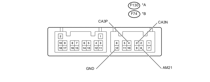
Text in Illustration *A w/ Stop and Start System *B w/o Stop and Start System
-
Disconnect the F130*1 or F74*2 power management control ECU connector.
-
Measure the resistance according to the value(s) in the table below.
for Sub Bus 15 Terminal No. (Symbol) Wiring Color Switch Condition Specified Condition F130-4 (CA3P) - F130-3 (CA3N)*1
F74-4 (CA3P) - F74-3 (CA3N)*2
Y - W Ignition switch off 108 to 132 Ω F130-4 (CA3P) - F130-8 (AM21)*1
F74-4 (CA3P) - F74-8 (AM21)*2
Y - B*1
Y - BE*2
Ignition switch off 6 kΩ or higher F130-3 (CA3N) - F130-8 (AM21)*1
F74-3 (CA3N) - F74-8 (AM21)*2
W - B*1
W - BE*2
Ignition switch off 6 kΩ or higher F130-4 (CA3P) - F130-12 (GND)*1
F74-4 (CA3P) - F74-12 (GND)*2
Y - BR Ignition switch off 200 Ω or higher F130-3 (CA3N) - F130-12 (GND)*1
F74-3 (CA3N) - F74-12 (GND)*2
W - BR Ignition switch off 200 Ω or higher
-
*1: w/ Stop and Start System
-
*2: w/o Stop and Start System
-
-
-
CHECK MAIN BODY ECU (MULTIPLEX NETWORK BODY ECU), INSTRUMENT PANEL JUNCTION BLOCK ASSEMBLY
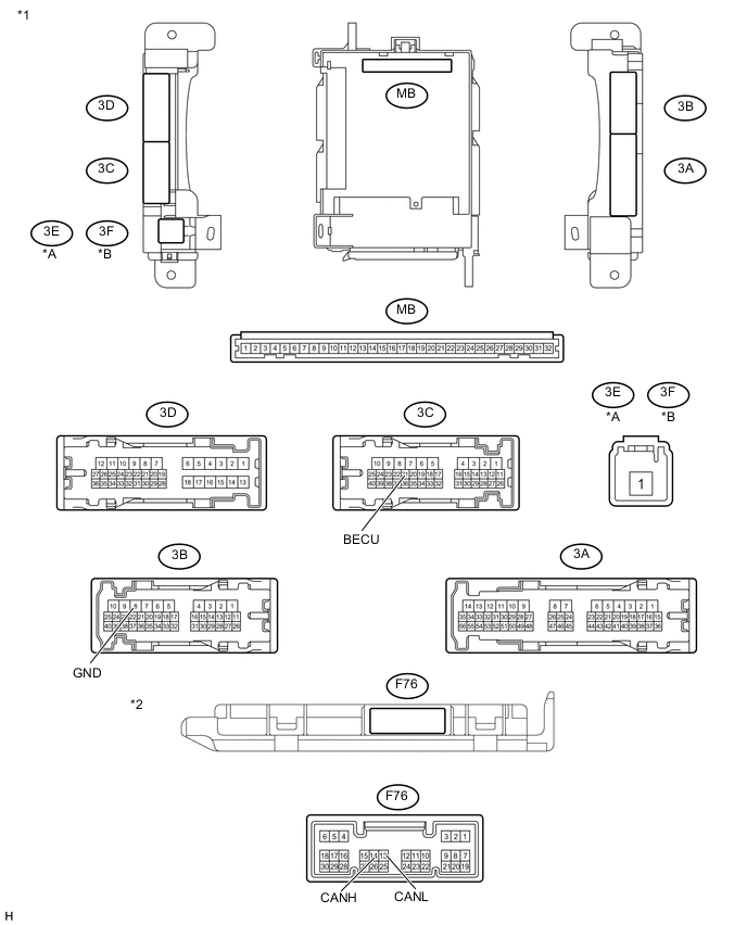
Text in Illustration *A for LHD *B for RHD *1 Instrument Panel Junction Block Assembly *2 Main Body ECU (Multiplex Network Body ECU)
-
Disconnect the F76 main body ECU (multiplex network body ECU) connector.
-
Disconnect the 3B and 3C instrument panel junction block assembly connectors.
-
Measure the resistance according to the value(s) in the table below.
for Bus 2 Terminal No. (Symbol) Wiring Color Switch Condition Specified Condition F76-14 (CANH) - F76-13 (CANL) R - W Ignition switch off 54 to 69 Ω F76-14 (CANH) - 3C-21 (BECU) R - L Ignition switch off 6 kΩ or higher F76-13 (CANL) - 3C-21 (BECU) W - L Ignition switch off 6 kΩ or higher F76-14 (CANH) - 3B-8 (GND1) R - W-B Ignition switch off 200 Ω or higher F76-13 (CANL) - 3B-8 (GND1) W - W-B Ignition switch off 200 Ω or higher
-
-
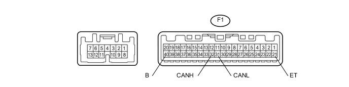
CHECK COMBINATION METER ASSEMBLY
-
Disconnect the F1 combination meter assembly connector.
-
Measure the resistance according to the value(s) in the table below.
for Bus 2 Terminal No. (Symbol) Wiring Color Switch Condition Specified Condition F1-32 (CANH) - F1-31 (CANL) G - W Ignition switch off 108 to 132 Ω F1-32 (CANH) - F1-40 (B) G - L Ignition switch off 6 kΩ or higher F1-31 (CANL) - F1-40 (B) W - L Ignition switch off 6 kΩ or higher F1-32 (CANH) - F1-21 (ET) G - W-B Ignition switch off 200 Ω or higher F1-31 (CANL) - F1-21 (ET) W - W-B Ignition switch off 200 Ω or higher
-
-
CHECK SKID CONTROL ECU (BRAKE ACTUATOR ASSEMBLY)
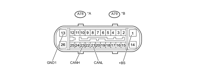
Text in Illustration *A for LHD with CVT and RHD *B except LHD with CVT
-
Disconnect the A78*1 or A79*2 skid control ECU (brake actuator assembly) connector.
-
Measure the resistance according to the value(s) in the table below.
for Bus 2 Terminal No. (Symbol) Wiring Color Switch Condition Specified Condition A78-23 (CANH) - A78-21 (CANL)*1
A79-23 (CANH) - A79-21 (CANL)*2
G - W Ignition switch off 54 to 69 Ω A78-23 (CANH) - A78-1 (+BS)*1
A79-23 (CANH) - A79-1 (+BS)*2
G - W Ignition switch off 6 kΩ or higher A78-21 (CANL) - A78-1 (+BS)*1
A79-21 (CANL) - A79-1 (+BS)*2
W - W Ignition switch off 6 kΩ or higher A78-23 (CANH) - A78-13 (GND1)*1
A79-23 (CANH) - A79-13 (GND1)*2
G - W-B Ignition switch off 200 Ω or higher A78-21 (CANL) - A78-13 (GND1)*1
A79-21 (CANL) - A79-13 (GND1)*2
W - W-B Ignition switch off 200 Ω or higher *1: for LHD with CVT and RHD
*2: except LHD with CVT
-
-
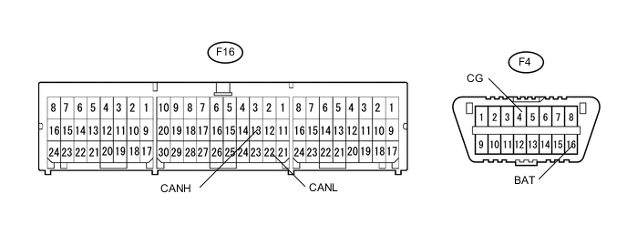
CHECK CENTER AIRBAG SENSOR ASSEMBLY
-
Disconnect the F16 center airbag sensor assembly connector.
-
Measure the resistance according to the value(s) in the table below.
for Bus 2 Terminal No. (Symbol) Wiring Color Switch Condition Specified Condition F16-13 (CANH) - F16-22 (CANL) B - W Ignition switch off 54 to 69 Ω F16-13 (CANH) - F4-16 (BAT) B - BE Ignition switch off 6 kΩ or higher F16-22 (CANL) - F4-16 (BAT) W - BE Ignition switch off 6 kΩ or higher F16-13 (CANH) - F4-4 (CG) B - W-B Ignition switch off 200 Ω or higher F16-22 (CANL) - F4-4 (CG) W - W-B Ignition switch off 200 Ω or higher
-
-
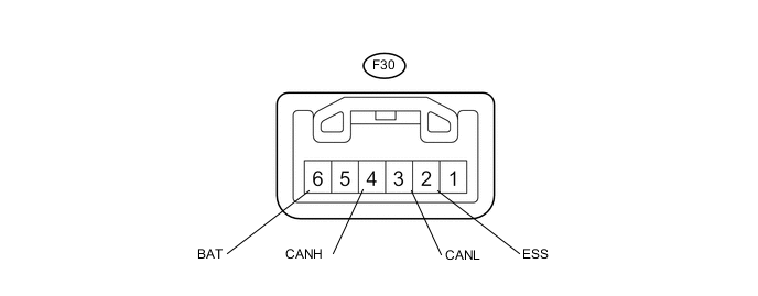
CHECK STEERING ANGLE SENSOR (SPIRAL CABLE SUB-ASSEMBLY)
-
Disconnect the F30 steering angle sensor (spiral cable sub-assembly) connector.
-
Measure the resistance according to the value(s) in the table below.
for Bus 2 Terminal No. (Symbol) Wiring Color Switch Condition Specified Condition F30-4 (CANH) - F30-3 (CANL) P - W Ignition switch off 54 to 69 Ω F30-4 (CANH) - F30-6 (BAT) P - SB Ignition switch off 6 kΩ or higher F30-3 (CANL) - F30-6 (BAT) W - SB Ignition switch off 6 kΩ or higher F30-4 (CANH) - F30-2 (ESS) P - BR Ignition switch off 200 Ω or higher F30-3 (CANL) - F30-2 (ESS) W - BR Ignition switch off 200 Ω or higher
-
-
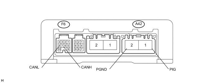
CHECK POWER STEERING ECU ASSEMBLY
-
Disconnect the A42 and F6 power steering ECU assembly connectors.
-
Measure the resistance according to the value(s) in the table below.
for Bus 2 Terminal No. (Symbol) Wiring Color Switch Condition Specified Condition F6-7 (CANH) - F6-8 (CANL) LG - W Ignition switch off 54 to 69 Ω F6-7 (CANH) - A42-1 (PIG) LG - W Ignition switch off 6 kΩ or higher F6-8 (CANL) - A42-1 (PIG) W - W Ignition switch off 6 kΩ or higher F6-7 (CANH) - A42-2 (PGND) LG - W-B Ignition switch off 200 Ω or higher F6-8 (CANL) - A42-2 (PGND) W - W-B Ignition switch off 200 Ω or higher
-
-
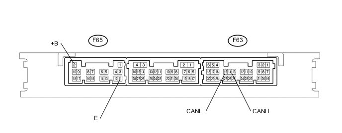
CHECK CERTIFICATION ECU (SMART KEY ECU ASSEMBLY) (w/ Entry and Start System)
-
Disconnect the F63 and F65 certification ECU (smart key ECU assembly) connectors.
-
Measure the resistance according to the value(s) in the table below.
for Bus 2 Terminal No. (Symbol) Wiring Color Switch Condition Specified Condition F63-14 (CANH) - F63-15 (CANL) L - W Ignition switch off 54 to 69 Ω F63-14 (CANH) - F65-2 (+B) L - W Ignition switch off 6 kΩ or higher F63-15 (CANL) - F65-2 (+B) W - W Ignition switch off 6 kΩ or higher F63-14 (CANH) - F65-11 (E) L - BR Ignition switch off 200 Ω or higher F63-15 (CANL) - F65-11 (E) W - BR Ignition switch off 200 Ω or higher
-
-
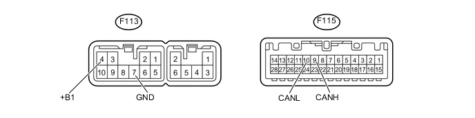
RADIO AND DISPLAY RECEIVER ASSEMBLY (w/ Display)
-
Disconnect the F113 and F115 radio and display receiver assembly connectors.
-
Measure the resistance according to the value(s) in the table below.
for Bus 3 Terminal No. (Symbol) Wiring Color Switch Condition Specified Condition F115-9 (CANH) - F115-10 (CANL) BE - W Ignition switch off 54 to 69 Ω F115-9 (CANH) - F113-4 (+B1) BE - SB Ignition switch off 6 kΩ or higher F115-10 (CANL) - F113-4 (+B1) W - SB Ignition switch off 6 kΩ or higher F115-9 (CANH) - F113-7 (GND1) BE - BR Ignition switch off 200 Ω or higher F115-10 (CANL) - F113-7 (GND1) W - BR Ignition switch off 200 Ω or higher
-
-
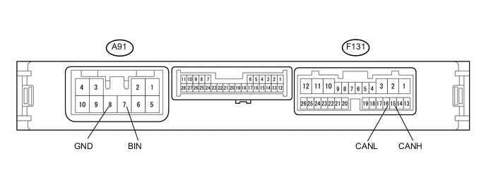
CHECK ENGINE STOP AND START ECU (w/ Stop and Start System)
-
Disconnect the A91 and F131 engine stop and start ECU connectors.
-
Measure the resistance according to the value(s) in the table below.
for Bus 2 Terminal No. (Symbol) Wiring Color Switch Condition Specified Condition F131-15 (CANH) - F131-16 (CANL) BE - W Ignition switch off 54 to 69 Ω F131-15 (CANH) - A91-7 (BIN) BE - B Ignition switch off 6 kΩ or higher F131-16 (CANL) - A91-7 (BIN) W - B Ignition switch off 6 kΩ or higher F131-15 (CANH) - A91-8 (GND) BE - W-B Ignition switch off 200 Ω or higher F131-16 (CANL) - A91-8 (GND) W - W-B Ignition switch off 200 Ω or higher
-
-
CHECK AIR CONDITIONING AMPLIFIER ASSEMBLY (w/ Air Conditioning System or PTC Heater)
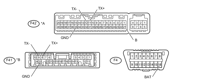
Text in Illustration *A w/ Automatic Air Conditioning System *B w/ Manual Air Conditioning System or PTC Heater
-
Disconnect the F42*1 or F41*2 air conditioning amplifier assembly connector.
-
Measure the resistance according to the value(s) in the table below.
for Bus 2 Terminal No. (Symbol) Wiring Color Switch Condition Specified Condition F42-11 (TX+) - F42-12 (TX-)*1
F41-8 (TX+) - F41-9 (TX-)*2
V - W Ignition switch off 54 to 69 Ω F42-11 (TX+) - F42-21 (B)*1
F41-8 (TX+) - F4-16 (BAT)*2
V - BE Ignition switch off 6 kΩ or higher F42-12 (TX-) - F42-21 (B)*1
F41-9 (TX-) - F4-16 (BAT)*2
W - BE Ignition switch off 6 kΩ or higher F42-11 (TX+) - F42-14 (GND)*1
F41-8 (TX+) - F41-23 (GND)*2
V - W-B Ignition switch off 200 Ω or higher F42-12 (TX-) - F42-14 (GND)*1
F41-9 (TX-) - F41-23 (GND)*2
W - W-B Ignition switch off 200 Ω or higher
-
*1: w/ Automatic Air Conditioning System
-
*2: w/ Manual Air Conditioning System or PTC Heater
-
-
-
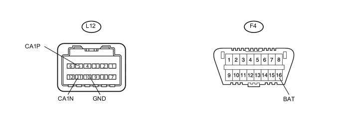
CHECK PRE-CRASH SAFETY CITY SENSOR
-
Disconnect the L12 pre-crash safety city sensor connector.
-
Measure the resistance according to the value(s) in the table below.
for Bus 2 Terminal No. (Symbol) Wiring Color Switch Condition Specified Condition L12-5 (CA1P) - L12-11 (CA1N) R - W Ignition switch off 54 to 69 Ω L12-5 (CA1P) - F4-16 (BAT) R - BE Ignition switch off 6 kΩ or higher L12-11 (CA1N) - F4-16 (BAT) W - BE Ignition switch off 6 kΩ or higher L12-5 (CA1P) - L12-10 (GND) R - W-B Ignition switch off 200 Ω or higher L12-11 (CA1N) - L12-10 (GND) W - W-B Ignition switch off 200 Ω or higher
-