CAN COMMUNICATION SYSTEM(w/ Toyota Safety Sense) SYSTEM DESCRIPTION
-
BRIEF DESCRIPTION
-
The Controller Area Network (CAN) is a serial data communication system for real time application. It is a vehicle multiplex communication system which has a high communication speed and the ability to detect malfunctions.
-
Using the CANH and CANL bus lines as a pair, CAN communication is performed using a voltage differential. (A base voltage is applied to the pair of lines and a voltage differential is created when communicating.)
-
Many ECUs or sensors installed on the vehicle operate by sharing information and communicating with each other.
-
The V bus has termination circuits with two resistors of 60 Ω, and the bus 2 and bus 3 have termination circuits with two resistors of 120 Ω.
-
Control system CAN is composed of 3 buses.
-
-
DEFINITION OF TERMS
-
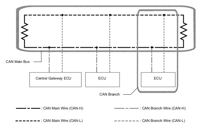
Main bus
-
The main bus is a wire harness between the two terminating resistors on the bus. This is the main bus in the CAN communication system.
-
-
Branch
-
A branch is a wire harness which diverges from the main bus to an ECU or sensor.
-
-
Terminating resistors
-
Two resistors of 120 Ω are installed in parallel across the ends of the CAN main bus lines. They are called terminating resistors. These resistors allow the changes of the voltage differential between the CAN bus lines to be accurately judged. To allow proper function of CAN communication, it is necessary to have both terminating resistors installed. Since the two resistors are installed in parallel, this results in a measurement of approximately 60 Ω.
-
-
-
ECUS OR SENSORS WHICH COMMUNICATE VIA CAN COMMUNICATION SYSTEM
-
V Bus
-
Central gateway ECU (network gateway ECU)
-
-
Bus 2
-
ECM
-
Center airbag sensor assembly
-
Skid control ECU (brake actuator assembly)
-
Engine stop and start ECU*1
-
Certification ECU (smart key ECU assembly)*2
-
Steering angle sensor (spiral cable sub-assembly)
-
Air conditioning amplifier assembly*3
-
Main body ECU (multiplex network body ECU)
-
Power steering ECU assembly
-
Combination meter assembly
-
Pre-crash safety city sensor
-
-
Bus 3
-
Radio and display receiver assembly*4
-
-
Sub Bus 15*5
-
ECM
-
Power management control ECU
-
*1: w/ Stop and Start System
-
*2: w/ Entry and Start System
-
*3: w/ Air Conditioning System or PTC Heater
-
*4: w/ Display
-
*5: for 1NR-FE
-
-
-
-
CIRCUIT DESCRIPTION
-
The bus 2, bus 3 and sub bus 15 each have termination circuits with two resistors of 120 Ω.
-
-
TROUBLESHOOTING REMARKS
-
DTCs for the CAN communication system can be checked using the GTS. The DLC3 is connected to the CAN communication system, but no DTCs exist regarding problems in the DLC3 or the DLC3 main lines. If there is any trouble in the DLC3 or the DLC3 main lines, ECUs on the CAN cannot output DTCs to the GTS.
-
-
DIAGNOSTIC TROUBLE CODES FOR CAN COMMUNICATION SYSTEM
Tech Tips
See Diagnosis System Click here.
-
HOW TO DISTINGUISH CONNECTOR OF CAN JUNCTION CONNECTOR
-
In the CAN communication system, the shape of connectors connected to the CAN junction connector which has a ground terminal is the same. The connectors connected to the CAN junction connector can be distinguished by the colors of the bus lines and the connecting side of the junction connector.
Tech Tips
See Terminals of ECU for bus line color or the shape of connecting surface Click here.
-