MAIN BODY ECU REMOVAL
PROCEDURE
-
PRECAUTION
Note
After turning the ignition switch off, waiting time may be required before disconnecting the cable from the battery terminal. Therefore, make sure to read the disconnecting the cable from the battery terminal notice before proceeding with work.( Click here)
-
DISCONNECT CABLE FROM NEGATIVE BATTERY TERMINAL
-
REMOVE UPPER INSTRUMENT PANEL SUB-ASSEMBLY (for LHD)
-
REMOVE LOWER NO. 2 INSTRUMENT PANEL FINISH PANEL (for LHD)
-
Disengage the 5 clips and the 2 claws and remove the instrument panel finish panel.
-
-
REMOVE GLOVE COMPARTMENT DOOR ASSEMBLY (for RHD)
Tech Tips
Use the same procedure as for the LHD side Click here.
-
SEPARATE INSTRUMENT PANEL WIRE
-
Remove the screw.
-
Disengage the clamp and remove the instrument panel wire.
-
-
REMOVE INSTRUMENT PANEL JUNCTION BLOCK ASSEMBLY
-
Disengage the clamps.
-
Disconnect the connectors on the front side of the instrument panel junction block.
-
Disconnect the main body ECU connector.
-
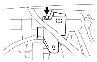
Remove the 2 bolts.
-
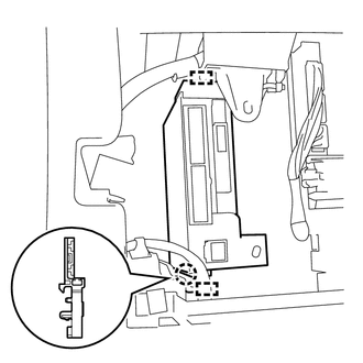
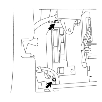
Disengage the claw and 2 clamps and separate the instrument panel junction block.
-
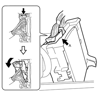
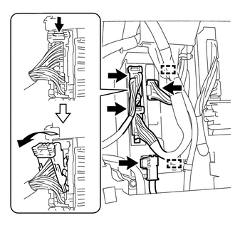
Disconnect the back side connector A indicated as shown in the illustration.
-
Text in Illustration *a Lever Slide the lever to the upward.
-
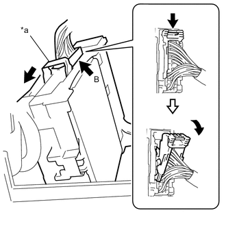
Disconnect the back side connector B indicated as shown in the illustration.
-
Remove the instrument panel junction block.
-
-
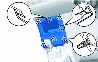
REMOVE JUNCTION BLOCK BRACKET
-
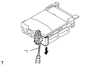
Text in Illustration *1 Protective Tape Using a screwdriver with its tip wrapped in protective tape, disengage the claw and remove the junction block bracket.
-
-
REMOVE JUNCTION BLOCK BRACKET
-
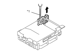
Text in Illustration *1 Protective Tape Using a screwdriver with its tip wrapped in protective tape, disengage the claw and remove the junction block bracket.
-
-
REMOVE MAIN BODY ECU
-
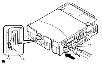
Text in Illustration *1 Protective Tape *2 Main Body ECU *3 Instrument Panel Junction Block Release the lock on the junction block side.
-
While pressing the lock on the junction block side, insert a screwdriver with its tip wrapped in protective tape between the main body ECU and the junction block.
Note
Use a thin-blade screwdriver with a diameter of 5.0 to 6.3 mm (0.197 to 0.248 in.), and with a length of 90 mm or more.
-
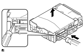
Do not pry the inserted screwdriver. Lift up the main body ECU to the point where the lock releases.
Note
-
Do not twist the screwdriver to raise the main body ECU.
-
If any terminals of the connectors, locking parts or cases are deformed or damaged, replace the instrument panel junction block assembly or the main body ECU.
-
-
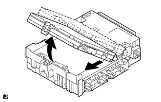
Remove the main body ECU by pulling it out from the junction block.
Note
Do not touch the main body ECU connector.
-