BATTERY CURRENT SENSOR(w/o Stop And Start System) INSPECTION
PROCEDURE
-
INSPECT BATTERY CURRENT SENSOR ASSEMBLY
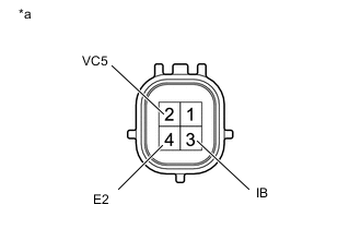
*a Component without harness connected
(Battery Current Sensor Assembly)
-
Check the resistance (current sensor).
-
Measure the resistance according to the value(s) in the table below.
Standard Resistance Tester Connection Condition Specified Condition 2 (VC5) - 4 (E2) Always 0.1 to 10 kΩ 2 (VC5) - 3 (IB) Below 0.5 kΩ 3 (IB) - 4 (E2) 0.05 to 10 kΩ If the result is not as specified, replace the battery current sensor assembly.
-
-
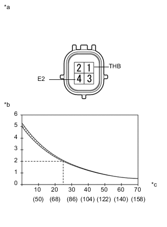
*a Component without harness connected
(Battery Current Sensor Assembly)
*b Resistance (kΩ) *c Temperature (°C (°F)) Check the resistance (thermistor).
-
Measure the resistance according to the value(s) in the table below.
Standard Resistance Tester Connection Condition Specified Condition 1 (THB) - 4 (E2) 20 to 30°C (68 to 86°F) 1.5 to 2.5 kΩ Tech Tips
The "Condition" indicates the temperature in the vicinity of the sensor, not of the actual sensor itself.
If the result is not as specified, replace the battery current sensor assembly.
-
-