LIN COMMUNICATION SYSTEM, Diagnostic DTC:B2786
| DTC Code | DTC Name |
|---|---|
| B2786 | No Response from Steering Lock ECU |
DESCRIPTION
This DTC is stored when LIN Communication between the certification ECU (smart key ECU assembly) and steering lock actuator assembly stops for more than 10 seconds.
| DTC No. | DTC Detection Condition | Trouble Area |
|---|---|---|
| B2786 | No communication between steering lock actuator assembly and certification ECU (smart key ECU assembly) for more than 10 seconds. |
|
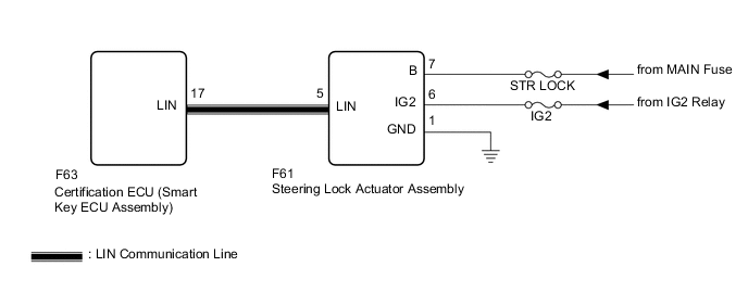
WIRING DIAGRAM
CAUTION / NOTICE / HINT
Note
-
Before replacing the certification ECU (smart key ECU assembly), refer to the entry and start system (for Entry Function) Click here.
-
If the steering lock actuator assembly is replaced, register the ECU code.
-
When using the intelligent tester to troubleshoot with the ignition switch off:
Connect the intelligent tester to the DLC3, and turn the courtesy switch on and off at 1.5-second intervals until communication between the intelligent tester and vehicle begins.
-
Inspect the fuses for circuits related to this system before performing the following inspection procedure.
Tech Tips
When communication between the steering lock actuator assembly and certification ECU (smart key ECU assembly) stops, DTC B2785 is also stored.
PROCEDURE
-
CLEAR DTC
-
Clear the DTC Click here.
NEXT 
-
-
CHECK FOR DTC
-
Check for DTC Click here.
Result Result Proceed to DTC B2786 is output A DTC B2786 and B2785 is output B
B 
GO TO DIAGNOSTIC TROUBLE CODE CHART Click here
A
-
-
CHECK HARNESS AND CONNECTOR (CERTIFICATION ECU (SMART KEY ECU ASSEMBLY) - STEERING LOCK ACTUATOR ASSEMBLY)
-
Disconnect the F63 certification ECU (smart key ECU assembly) connector.
-
Disconnect the F61 steering lock actuator assembly connector.
-
Measure the resistance according to the value(s) in the table below.
Standard Resistance Tester Connection Condition Specified Condition F63-17 (LIN) - F61-5 (LIN) Always Below 1 Ω F63-17 (LIN) or F61-5 (LIN) - Body ground Always 10 kΩ or higher
NG
REPAIR OR REPLACE HARNESS OR CONNECTOR
OK
-
-
CHECK HARNESS AND CONNECTOR (POWER SOURCE CIRCUIT)
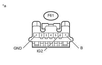
Text in Illustration *a Front view of wire harness connector
(to Steering Lock Actuator Assembly)
-
Measure the voltage according to the value(s) in the table below.
Standard Voltage Tester Connection Switch Condition Specified Condition F61-6 (IG2) - Body ground Ignition switch ON 11 to 14 V F61-7 (B) - Body ground Always 11 to 14 V -
Measure the resistance according to the value(s) in the table below.
Standard Resistance Tester Connection Condition Specified Condition F61-1 (GND) - Body ground Always Below 1 Ω
NG
REPAIR OR REPLACE HARNESS OR CONNECTOR (POWER SOURCE CIRCUIT)
OK
-
-
REPLACE STEERING LOCK ACTUATOR ASSEMBLY
-
Replace the steering lock actuator assembly.
-
for RHD Click here
-
for LHD Click here
-
NEXT
-
-
CHECK DTC OUTPUT
-
Clear the DTC Click here.
-
Recheck for DTCs.
Result Result Proceed to DTC B2786 is not output A DTC B2786 is output B
A
END (STEERING LOCK ACTUATOR ASSEMBLY WAS DEFECTIVE)
B
REPLACE CERTIFICATION ECU (SMART KEY ECU ASSEMBLY)
-