CHARGING SYSTEM(w/o Stop And Start System), Diagnostic DTC:P161A
| DTC Code | DTC Name |
|---|---|
| P161A | Lost Communication with Alternator |
DESCRIPTION
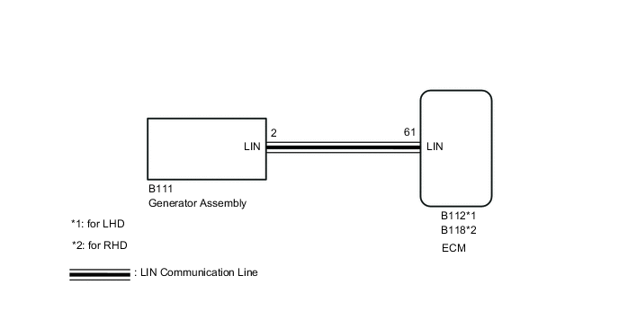
The generator assembly communicates with the ECM through the LIN communication system.
| DTC No. | Detection Item | DTC Detection Condition | Trouble Area | Warning Indicate | Memory |
|---|---|---|---|---|---|
| P161A | Lost Communication with Alternator | Generator assembly or ECM communication stop for about 17.5 minutes or more with the ignition switch ON (1 trip detection logic) |
|
Charge warning light does not come on | DTC stored |
WIRING DIAGRAM
CAUTION / NOTICE / HINT
Note
Before replacing the ECM, refer to Service Bulletin.
PROCEDURE
-
CHECK CHARGING SYSTEM
-
Check the charging system.
Result Proceed to OK NG
NG 
REPAIR OR REPLACE CHARGING SYSTEM
OK 
-
-
CHECK HARNESS AND CONNECTOR (GENERATOR ASSEMBLY - ECM)
-
Disconnect the B112 ECM connector (for LHD).
-
Disconnect the B118 ECM connector (for RHD).
-
Disconnect the B111 generator assembly connector.
-
Measure the resistance according to the value(s) in the table below.
for LHD Tester Connection Condition Specified Condition B111-2 (LIN) - B112-61 (LIN) Always Below 1 Ω B111-2 (LIN) or B112-61 (LIN) - Body ground Always 10 kΩ or higher for RHD Tester Connection Condition Specified Condition B111-2 (LIN) - B118-61 (LIN) Always Below 1 Ω B111-2 (LIN) or B118-61 (LIN) - Body ground Always 10 kΩ or higher Result Proceed to OK NG
NG
REPAIR OR REPLACE HARNESS OR CONNECTOR
OK
-
-
INSPECT ECM
-
Reconnect the B112 ECM connector (for LHD).
-
Reconnect the B118 ECM connector (for RHD).
-
Turn the ignition switch to ON.
-
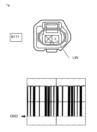
*a Front view of wire harness connector
(to Generator Assembly)
Using an oscilloscope, check the waveform.
Measurement Condition Item Content Tester Connection B111-2 (LIN) - Body ground) Tool Setting 2 V/DIV., 20 ms./DIV. Condition Ignition switch ON OK Waveform is similar to that shown in the illustration. Result Proceed to OK NG
OK
REPLACE GENERATOR ASSEMBLY Click here
NG
REPLACE ECM Click here
-