CHARGING SYSTEM(w/ Stop And Start System), Diagnostic DTC:P058A
| DTC Code | DTC Name |
|---|---|
| P058A | Battery Monitor Module Performance |
DESCRIPTION
The battery state sensor assembly detects the voltage, current and temperature of the battery. The battery state sensor assembly calculates State of Charge (SOC) based on the voltage and current of the battery and sends it to the ECM. Based on the signals received, the ECM adjusts the charging voltage of the generator assembly. The battery state sensor assembly calculates the battery temperature based on changes in resistance of a built-in thermistor and sends it to the ECM. The ECM reduces the amount of charging current based on this signal in order to protect the battery.
| DTC No. | Detection Item | DTC Detection Condition | Trouble Area | Warning Indicate | Memory |
|---|---|---|---|---|---|
| P058A | Battery Monitor Module Performance | Any of the following conditions is met with the ignition switch ON. (1 trip detection logic):
|
|
Charge warning light does not come on | DTC stored |
WIRING DIAGRAM
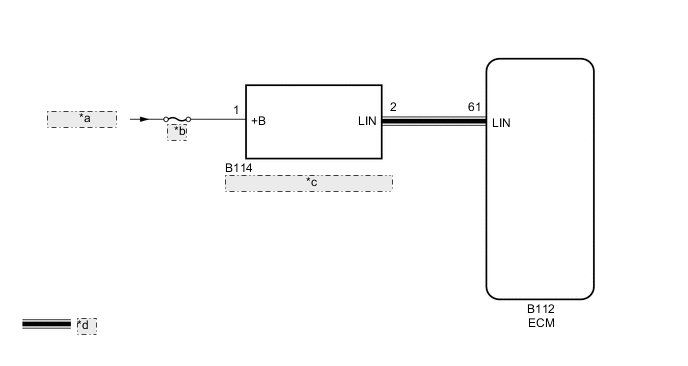
| *a | from Battery |
| *b | ICS |
| *c | Battery State Sensor Assembly |
| *d | LIN Communication Line |
CAUTION / NOTICE / HINT
Note
-
Inspect the fuses for circuits related to this system before performing the following inspection procedure.
-
When P162B (Lost Communication with Battery Monitor Module) is output at the same time, perform the inspection for P162B (Lost Communication with Battery Monitor Module) first.
PROCEDURE
-
CHECK BATTERY STATE SENSOR ASSEMBLY INSTALLATION
-
Check the installation condition of the battery state sensor assembly.
Result Proceed to OK NG
NG 
INSTALL BATTERY STATE SENSOR ASSEMBLY CORRECTLY Click here
OK 
-
-
CHECK CHARGING SYSTEM
-
Check the charging system.
Result Result OK NG
NG
REPAIR OR REPLACE CHARGING SYSTEM
OK
-
-
CHECK HARNESS AND CONNECTOR (POWER SOURCE CIRCUIT)
-
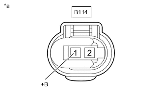
*a Front view of wire harness connector
(to Battery State Sensor Assembly)
Disconnect the battery state sensor assembly connector.
-
Measure the voltage according to the value(s) in the table below.
Standard Voltage Tester Connection Switch Condition Specified Condition B114-1 (+B) - Body ground Ignition switch ON 11 to 14 V Result Result OK NG
OK
REPLACE BATTERY STATE SENSOR ASSEMBLY Click here
NG
REPAIR OR REPLACE HARNESS OR CONNECTOR
-