GENERATOR(for TMC Made except Cold Area Specification Vehicles) REASSEMBLY

PROCEDURE
-
INSTALL GENERATOR ROTOR ASSEMBLY
-
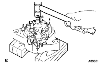
Place the generator rotor assembly on the generator drive end frame assembly.
-
Using a plastic hammer, install the generator rotor assembly to the generator drive end frame assembly.
-
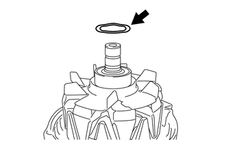
Install a new generator washer on the generator rotor assembly.
-
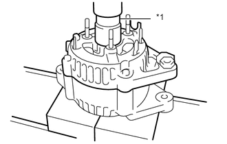
Text in Illustration *1 29mm/12pt Socket Wrench Using a 29mm/12pt socket wrench and press, slowly press in the generator rectifier end frame.
-
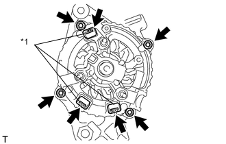
Text in Illustration *1 Terminal Insulator Install the 4 nuts.
- Torque:
- 4.5 N*m { 46 kgf*cm, 40 in.*lbf }
-
Install the 3 terminal insulators onto the generator rectifier end frame.
-
-
INSTALL GENERATOR HOLDER WITH RECTIFIER
-
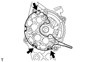
Install the generator holder with rectifier with the 3 screws.
- Torque:
- 2.0 N*m { 20 kgf*cm, 18 in.*lbf }
-
-
INSTALL GENERATOR REGULATOR ASSEMBLY
-
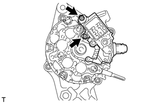
Install the generator regulator assembly with the 2 screws.
- Torque:
- 2.0 N*m { 20 kgf*cm, 18 in.*lbf }
-
-
INSTALL GENERATOR BRUSH HOLDER ASSEMBLY
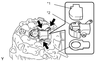
Text in Illustration *1 Generator Brush Cover *2 Generator Brush Holder Assembly *3 Generator Plate Seal
-
Install the generator plate seal.
-
Install the generator brush holder assembly with the 3 screws.
- Torque:
- 2.0 N*m { 20 kgf*cm, 18 in.*lbf }
-
Install the generator brush cover onto the generator brush holder assembly.
-
-
INSTALL GENERATOR REAR END COVER
-
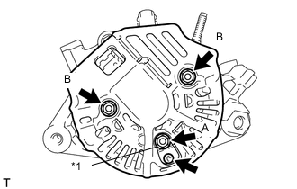
Text in Illustration *1 Rectifier Plate Install the generator rear end cover with the 2 nuts B.
- Torque:
- 4.4 N*m { 45 kgf*cm, 39 in.*lbf }
- for nut B
-
Install the rectifier plate with the nut A and screw.
- Torque:
- 4.4 N*m { 45 kgf*cm, 39 in.*lbf }
- for nut A
- Torque:
- 3.9 N*m { 40 kgf*cm, 35 in.*lbf }
- for screw
-
-
INSTALL GENERATOR TERMINAL INSULATOR
-
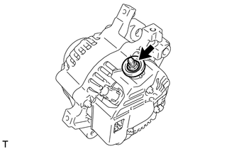
Install the generator terminal insulator with the nut.
- Torque:
- 4.1 N*m { 42 kgf*cm, 36 in.*lbf }
-
-
INSTALL GENERATOR CLUTCH PULLEY
-
Temporarily install the clutch pulley onto the rotor shaft.
-
Clamp the generator housing stay in a vise tightly.
-
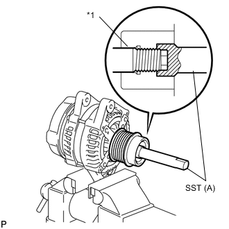
Text in Illustration *1 Rotor Shaft Place the rotor shaft end into SST (A).
- SST
- 09820-63021
-
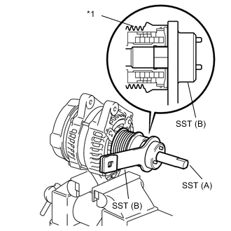
Text in Illustration *1 Clutch Pulley Fit SST (B) to the generator clutch pulley.
-
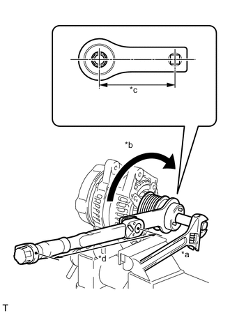
Text in Illustration *a Hold *b Turn *c Length 100 mm *d Length 318 mm Tighten the pulley by turning SST (B) in the direction shown in the illustration.
- Torque:
- without SST
- 80 N*m { 816 kgf*cm, 59 ft.*lbf }
- with SST
- 61 N*m { 622 kgf*cm, 45 ft.*lbf }
Note
-
Check that the generator drive end frame assembly is secured in the vise tightly.
-
Hold SST (A) tightly during the operation.
Tech Tips
-
Use a torque wrench with a fulcrum length of 318 mm (12.52 in.).
-
This torque value is effective when SST 100 mm (5.12 in.) is parallel to the torque wrench.
-
Remove SST from the generator assembly.
-
Check that the generator clutch pulley rotates smoothly.
-
-
INSTALL GENERATOR PULLEY CAP
-
Install a new generator pulley cap onto the generator clutch pulley.
-