CHARGING SYSTEM TERMINALS OF ECU
-
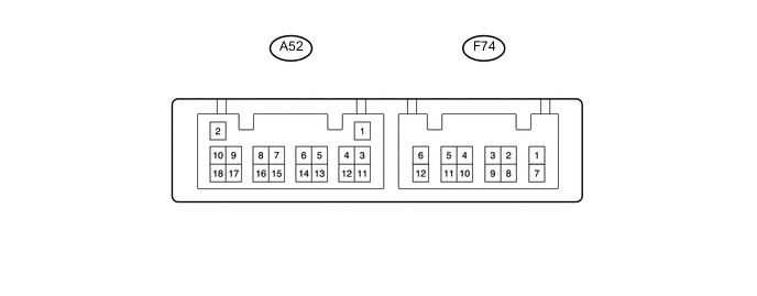
CHECK POWER MANAGEMENT CONTROL ECU (w/o Stop and Start System)
-
Disconnect the A52 and F74 power management control ECU connectors.
-
Measure the resistance and voltage according to the value(s) in the table below.
Terminal No. (Symbol) Wiring Color Condition Specified Condition F74-8 (AM21) - Body ground BE - Body ground Always 11 to 14 V A52-17 (LIN1) - Body ground Y - Body ground Always 10 kΩ or higher F74-12 (GND) - Body ground BR - Body ground Always Below 1 Ω If the result is not as specified, the ECU may have a malfunction.
-
Reconnect the power management control ECU connectors.
-
Measure the resistance, voltage and waveform according to the value(s) in the table below.
Terminal No. (Symbol) Wiring Color Terminal Description Condition Specified Condition A52-12 (VC) - A52-18 (E2) P - V Power source of battery current sensor assembly Ignition switch ON 4.5 to 5.5 V A52-15 (THB) - A52-18 (E2) SB - V Battery temperature sensor Ignition switch ON 0.2 to 4.8 V A52-13 (IB) - A52-18 (E2) L - V Battery current sensor Ignition switch ON 0.2 to 4.8 V A52-18 (E2) - Body ground V - Body ground Body ground (Battery current sensor) Ignition switch ON, engine stopped Below 1 Ω A52-5 (STA) - F74-12 (GND) P - BR Starter operation signal Cranking 6 V or higher F74-8 (AM21) - F74-12 (GND) BE - BR Battery power Always 11 to 14 V F74-1 (INH) - F74-12 (GND) L - BR Windshield wiper switch assembly Ignition switch ON
Windshield wiper switch "HI" position
11 to 14 V F74-2 (IG2) - F74-12 (GND) GR - BR Ignition switch signal Ignition switch ON 11 to 14 V If the result is not as specified, the ECU may have a malfunction.
-
-
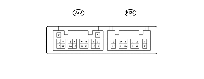
CHECK POWER MANAGEMENT CONTROL ECU (w/ Stop and Start System)
-
Disconnect the A90 and F130 power management control ECU connectors.
-
Measure the resistance and voltage according to the value(s) in the table below.
Terminal No. (Symbol) Wiring Color Condition Specified Condition F130-8 (AM21) - Body ground B - Body ground Always 11 to 14 V A90-17 (LIN1) - Body ground Y - Body ground Always 10 kΩ or higher F130-12 (GND) - Body ground BR - Body ground Always Below 1 Ω If the result is not as specified, the ECU may have a malfunction.
-
Reconnect the power management control ECU connectors.
-
Measure the resistance, voltage and waveform according to the value(s) in the table below.
Terminal No. (Symbol) Wiring Color Terminal Description Condition Specified Condition A90-12 (VC) - A90-18 (E2) P - V Power source of battery current sensor assembly Ignition switch ON 4.5 to 5.5 V A90-15 (THB) - A90-18 (E2) SB - V Battery temperature sensor Ignition switch ON 0.2 to 4.8 V A90-13 (IB) - A90-18 (E2) L - V Battery current sensor Ignition switch ON 0.2 to 4.8 V A90-18 (E2) - Body ground V - Body ground Body ground (Battery current sensor) Ignition switch ON, engine stopped Below 1 Ω A90-5 (STA) - F130-12 (GND) P - BR Starter operation signal Cranking 6 V or higher F130-8 (AM21) - F130-12 (GND) B - BR Battery power Always 11 to 14 V F130-1 (INH) - F130-12 (GND) L - BR Windshield wiper switch assembly Ignition switch ON
Windshield wiper switch "HI" position
11 to 14 V F130-2 (IG2) - F130-12 (GND) GR - BR Ignition switch signal Ignition switch ON 11 to 14 V If the result is not as specified, the ECU may have a malfunction.
-