CHARGING SYSTEM, Diagnostic DTC:P161A
| DTC Code | DTC Name |
|---|---|
| P161A | LIN Communication Error with Alternator |
DESCRIPTION
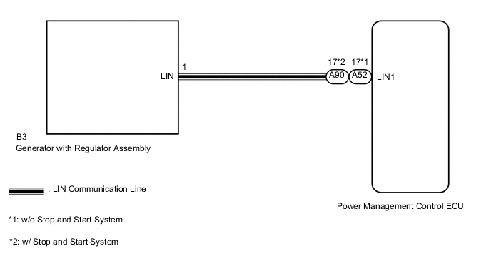
The generator with regulator assembly communicates with the power management control ECU through the LIN communication system.
| DTC No. | DTC Detection Condition | Trouble Area |
|---|---|---|
| P161A | Generator with regulator assembly, power management control ECU communication stop for about 18 minutes or more with the ignition switch ON (1-trip detection logic) |
|
WIRING DIAGRAM
CAUTION / NOTICE / HINT
Note
-
After repair or replacement, check to disappear DTC. It takes 20 minutes maximum to display DTC after turning the ignition switch to ON. So, confirm not to display DTC more than 20 minutes.
-
When rotational vibration of engine relating to electrical load is abnormally big, there is possibility of LIN communication error. Confirm whether DTC P161A is output for 20 minutes.
PROCEDURE
-
CHECK CHARGING SYSTEM
-
Check the charging system Click here.
NG 
REPAIR OR REPLACE CHARGING SYSTEM
OK 
-
-
SYSTEM CHECK
-
Check the vehicle specifications.
Result Result Proceed to w/o Stop and Start System A w/ Stop and Start System B
B 
CHECK HARNESS AND CONNECTOR (GENERATOR WITH REGULATOR ASSEMBLY - POWER MANAGEMENT CONTROL ECU) Click here
A
-
-
CHECK HARNESS AND CONNECTOR (GENERATOR WITH REGULATOR ASSEMBLY - POWER MANAGEMENT CONTROL ECU)
-
Disconnect the A52 power management control ECU connector.
-
Disconnect the B3 generator with regulator assembly connector.
-
Measure the resistance according to the value(s) in the table below.
Standard Resistance Tester Connection Condition Specified Condition B3-1 (LIN) - A52-17 (LIN1) Always Below 1 Ω B3-1 (LIN) - Body ground Always 10 kΩ or higher A52-17 (LIN1) - Body ground Always 10 kΩ or higher Result Result Proceed to NG A OK B
A
REPAIR OR REPLACE HARNESS OR CONNECTOR
B
INSPECT GENERATOR WITH REGULATOR ASSEMBLY Click here
-
-
CHECK HARNESS AND CONNECTOR (GENERATOR WITH REGULATOR ASSEMBLY - POWER MANAGEMENT CONTROL ECU)
-
Disconnect the A90 power management control ECU connector.
-
Disconnect the B3 generator with regulator assembly connector.
-
Measure the resistance according to the value(s) in the table below.
Standard Resistance Tester Connection Condition Specified Condition B3-1 (LIN) - A90-14 (LIN1) Always Below 1 Ω B3-1 (LIN) - Body ground Always 10 kΩ or higher A90-14 (LIN1) - Body ground Always 10 kΩ or higher Result Result Proceed to NG A OK (w/ Generator with Regulator Assembly for TMMF Made) B
A
REPAIR OR REPLACE HARNESS OR CONNECTOR
B
-
-
INSPECT GENERATOR WITH REGULATOR ASSEMBLY
-
Remove the generator with regulator assembly.
-
except Cold Area Specification Vehicles Click here
-
for Cold Area Specification Vehicles Click here
-
-
Inspect the generator with regulator assembly.
-
except Cold Area Specification Vehicles Click here
-
for Cold Area Specification Vehicles Click here
Result Result Proceed to NG (except Cold Area Specification Vehicles) A NG (for Cold Area Specification Vehicles) B OK C -
A
REPLACE GENERATOR WITH REGULATOR ASSEMBLY Click here
B
REPLACE GENERATOR WITH REGULATOR ASSEMBLY Click here
C
REPLACE POWER MANAGEMENT CONTROL ECU Click here
-