GENERATOR(for TMC Made except Cold Area Specification Vehicles) REASSEMBLY

PROCEDURE
-
INSTALL GENERATOR ROTOR ASSEMBLY
-
Place the generator drive end frame on the generator rotor assembly.
Note
Do not drop the generator rotor assembly.
-
Install the generator rotor assembly and plate retainer.
-
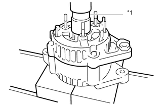
Text in Illustration *1 30 mm Socket Wrench Using a 30 mm socket wrench and press, slowly press in the rectifier end frame.
-
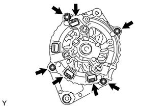
Install the 4 nuts.
- Torque:
- 4.5 N*m { 46 kgf*cm, 40 in.*lbf }
-
Install the 3 terminal insulators onto the rectifier end frame.
-
-
INSTALL GENERATOR HOLDER WITH RECTIFIER
-
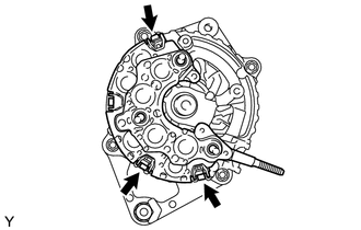
Install the generator rectifier holder with the 3 screws.
- Torque:
- 2.0 N*m { 20 kgf*cm, 17 in.*lbf }
-
-
INSTALL GENERATOR REGULATOR ASSEMBLY
-
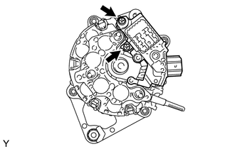
Install the generator regulator assembly with the 2 screws.
- Torque:
- 2.0 N*m { 20 kgf*cm, 17 in.*lbf }
-
-
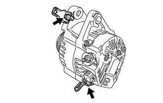
INSTALL GENERATOR BRUSH HOLDER ASSEMBLY
-
Install the plate seal.
-
Install the generator brush holder assembly with the 3 screws.
- Torque:
- 2.0 N*m { 20 kgf*cm, 17 in.*lbf }
-
Install the brush cover onto the generator brush holder assembly.
-
Install the rear end cover with the 2 nuts.
- Torque:
- 4.4 N*m { 45 kgf*cm, 39 in.*lbf }
-
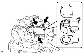
Install the rectifier plate with the nut and screw.
- Torque:
- 4.4 N*m { 45 kgf*cm, 39 in.*lbf }
- for nut
- Torque:
- 3.9 N*m { 40 kgf*cm, 34 in.*lbf }
- for screw
-
Install the terminal insulator with the nut.
- Torque:
- 4.1 N*m { 42 kgf*cm, 36 in.*lbf }
-
-
INSTALL GENERATOR PULLEY
Tech Tips
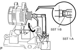
SST 1-A and B 09820 - 06010 SST 2 09820 - 06021 Text in Illustration *a Turn *b Hold
-
Clamp the generator housing stay in a vise.
-
Install the generator pulley onto the generator rotor shaft by tightening the generator pulley nut by hand.
-
Hold SST 1-A with a torque wrench, and tighten SST 1-B clockwise to the specified torque.
- SST
- 09820-63011 ( 09820-06010, 09820-06021 )
- Torque:
- 39 N*m { 398 kgf*cm, 29 ft.*lbf }
Note
Check that SST is securely fitted onto the generator rotor shaft.
-
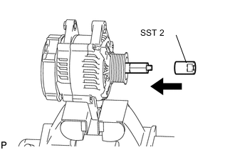
Insert SST 2, and attach the pulley nut to SST 2.
-
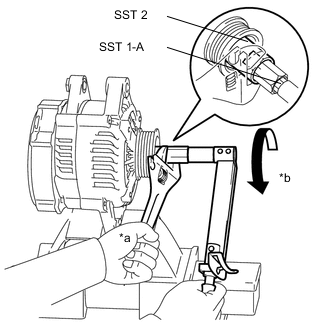
Text in Illustration *a Hold *b Turn Tighten the generator pulley nut by turning SST 1-A in the direction shown in the illustration.
- Torque:
- 133 N*m { 1356 kgf*cm, 98 ft.*lbf }
Tech Tips
Hold the adjustable wrench against the vise and tighten the nut securely.
-
Remove SST 2 from the generator.
-
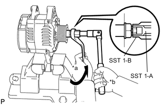
Text in Illustration *a Turn *b Hold Turn SST 1-B, and remove SST 1-A and B.
-
Turn the generator pulley, and check that the generator pulley moves smoothly.
-
-
INSTALL WIRE HARNESS CLAMP BRACKET
-
Install the wire harness clamp bracket with the 2 bolts.
- Torque:
- 8.4 N*m { 85 kgf*cm, 74 in.*lbf }
-