GENERATOR(for TMC Made except Cold Area Specification Vehicles) DISASSEMBLY

PROCEDURE
-
REMOVE WIRE HARNESS CLAMP BRACKET
-
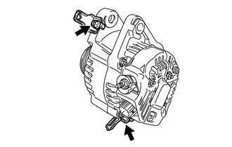
Remove the 2 bolts and remove the 2 wire harness clamp brackets.
-
-
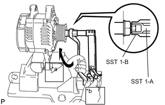
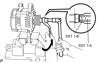
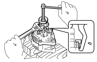
REMOVE GENERATOR PULLEY
- SST
- 09820-63011 ( 09820-06010, 09820-06021 )
Tech Tips
SST 1-A and B 09820 - 06010 SST 2 09820 - 06021 Text in Illustration *a Turn *b Hold
-
Clamp the generator housing stay in a vise.
-
Hold SST 1-A with a torque wrench, and tighten SST 1-B clockwise to the specified torque.
- Torque:
- 39 N*m { 400 kgf*cm, 29 ft.*lbf }
Note
Check that SST is securely fitted onto the generator rotor shaft.
-
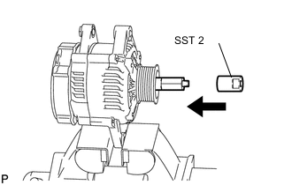
Insert SST 2, and attach the pulley nut to SST 2.
-
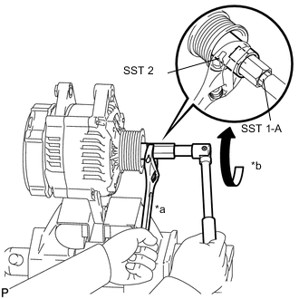
Text in Illustration *a Hold *b Turn To loosen the generator pulley nut, turn SST 1-A in the direction shown in the illustration.
Note
To prevent damage to the rotor shaft, do not loosen the generator pulley nut by more than one half turn.
-
Remove SST 2 from the generator.
-
Text in Illustration *a Turn *b Hold Turn SST 1-B, and remove SST 1-A and B.
-
Remove the generator pulley nut and generator pulley.
-
REMOVE GENERATOR BRUSH HOLDER ASSEMBLY
-
Remove the nut and terminal insulator.
-
Remove the nut, screw and rectifier plate.
-
Remove the 2 nuts and rear end cover.
-
Remove the brush cover from the generator brush holder assembly.
-
Remove the 3 screws and generator brush holder assembly.
-
Remove the plate seal.
-
-
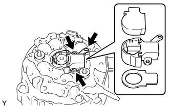
REMOVE GENERATOR REGULATOR ASSEMBLY
-
Remove the 2 screws and generator regulator assembly.
-
-
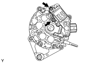
REMOVE GENERATOR HOLDER WITH RECTIFIER
-
Remove the 3 screws and generator holder with rectifier.
-
-
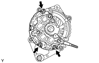
REMOVE GENERATOR ROTOR ASSEMBLY
-
Remove the 3 terminal insulators from the rectifier end frame.
-
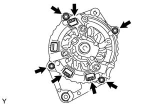
Remove the 4 nuts.
-
Text in Illustration *a Turn *b Hold Using SST, remove the rectifier end frame.
- SST
- 09286-46011
-
Remove the plate retainer.
-
Remove the generator rotor assembly from the drive end frame.
Note
Do not drop the generator rotor assembly.
Tech Tips
If the generator rotor is engaged too firmly, gently tap the generator rotor shaft to remove it using a plastic hammer.
-