NAVIGATION SYSTEM TERMINALS OF ECU
-
RADIO AND DISPLAY RECEIVER ASSEMBLY
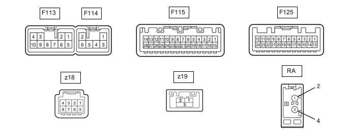
Terminal No. (Symbol) Wiring Color Terminal Description Condition Specified Condition F113-1 (FR+) - F113-7 (GND1) LG - BR Sound signal (Front Right) Audio system playing A waveform synchronized with sounds is output F113-2 (FL+) - F113-7 (GND1) P - BR Sound signal (Front Left) Audio system playing A waveform synchronized with sounds is output F113-3 (ACC1) - F113-7 (GND1) GR - BR Power source (ACC) Ignition switch off Below 1 V Ignition switch ACC 11 to 14 V F113-4 (+B1) - F113-7 (GND1) SB - BR Power source (+B) Always 11 to 14 V F113-5 (FR-) - F113-7 (GND1) L - BR Sound signal (Front Right) Audio system playing A waveform synchronized with sounds is output F113-6 (FL-) - F113-7 (GND1) V - BR Sound signal (Front Left) Audio system playing A waveform synchronized with sounds is output F113-7 (GND1) - Body ground BR - Body ground Ground Always Below 1 V F113-9 (AMP) - F113-7 (GND1)*1 SB - BR Power source of stereo component amplifier Audio system playing 11 to 14 V F113-10 (ILL+) - F113-7 (GND1) G - BR Illumination signal Light control switch off Below 1 V Light control switch in tail or head position 11 to 14 V F114-1 (RR+) - F113-7 (GND1) R - BR Sound signal (Rear Right) Audio system playing A waveform synchronized with sounds is output F114-2 (RL+) - F113-7 (GND1) B - BR Sound signal (Rear Left) Audio system playing A waveform synchronized with sounds is output F114-3 (RR-) - F113-7 (GND1) W - BR Sound signal (Rear Right) Audio system playing A waveform synchronized with sounds is output F114-6 (RL-) - F113-7 (GND1) Y - BR Sound signal (Rear Left) Audio system playing A waveform synchronized with sounds is output F115-1 (IG) - F113-7 (GND1) LG - BR Power source (IG) Ignition switch off Below 1 V Ignition switch ON 11 to 14 V F115-4 (MACC) - F113-7 (GND1) R - BR Microphone power supply Ignition switch off Below 1 V Ignition switch ACC 4 to 6 V F115-5 (MIN+) - F113-7 (GND1) B - BR Microphone voice signal See "Microphone Level Test" in Operation Check Click here
- F115-6 (SNS2) - F113-7 (GND1) GR - BR Microphone connection detection signal Always Below 1 V F115-9 (CANH) BE CAN communication signal - - F115-10 (CANL) W CAN communication signal - - F115-15 (PKB) - F113-7 (GND1) P - BR Parking brake signal See "Vehicle Signal Check Mode" in Operation Check Click here
- F115-17 (SPD) - F113-7 (GND1) V - BR Vehicle speed signal See "Vehicle Signal Check Mode" in Operation Check Click here
- F115-18 (SGND) - Body ground Shield - Body ground Shield ground Always Below 1 V F115-19 (MIN-) - F113-7 (GND1) W - BR Microphone voice signal See "Microphone Level Test" in Operation Check Click here
- F115-21 (SW1) - F113-7 (GND1) L - BR Steering pad switch signal Steering pad switch not operated 3.3 V or higher SEEK+ switch pushed Below 0.6 V SEEK- switch pushed Approximately 0.9 V VOL+ switch pushed Approximately 1.5 V VOL- switch pushed Approximately 2.4 V F115-22 (SW2) - F113-7 (GND1) P - BR Steering pad switch signal Steering pad switch not operated 3.3 V or higher MODE switch pushed Below 0.6 V On hook switch pushed Approximately 0.9 V Off hook switch pushed Approximately 1.5 V F115-23 (SWG) - F113-7 (GND1) R - BR Steering pad switch ground Always Below 1 V F125-3 (CNH1) P Local bus communication signal - - F125-4 (CNL1) W Local bus communication signal - - F125-11 (CA+) - F113-7 (GND1) R - BR Television camera power supply Ignition switch ON
Shift lever in R
5.5 to 7.05 V F125-12 (V+) - F113-7 (GND1) B - BR Television camera image signal Ignition switch ON
Shift lever in R
Camera lens is not covered, displaying an image
Pulse generation
(Refer to waveform 1)
Ignition switch ON
Shift lever in R
Camera lens is covered, blacking out screen
Pulse generation
(Refer to waveform 2)
F125-23 (CGND) - Body ground Shield - Body ground Shield ground Always Below 1 V F125-24 (V-) - F113-7 (GND1) W - BR Ground Always Below 1 V z18-1 (SGND) - Body ground Shield - Body ground Shield ground Always Below 1 V z18-2 (SPDO) - F113-7 (GND1) B - BR Vehicle speed signal See "Check Vehicle Signal" in Operation Check
- z18-3 (ACC2) - F113-7 (GND1) B - BR Power source (ACC) Ignition switch off Below 1 V Ignition switch ACC 11 to 14 V z18-4 (+B2) - F113-7 (GND1) W - BR Power source (+B) Always 11 to 14 V z18-5 (MIC+) - F113-7 (GND1) B - BR Microphone voice signal See "Check Microphone" in Operation Check
- z18-6 (MIC-) - F113-7 (GND1) B - BR Microphone voice signal See "Check Microphone" in Operation Check
- z18-8 (GND2) - Body ground W - Body ground Ground Always Below 1 V Z19-1 (LV1-) - Video signal (Digital) - - Z19-2 (LV1+) - Video signal (Digital) - - Z19-3 (LVG1) - Shield ground - - RA-5 (ANT+) - Body ground # - Body ground Power source of antenna Ignition switch ACC
Radio switch on and FM or AM selected
11 to 14 V
-
*1: for 8 Speakers
-
#: There is no wire color information
-
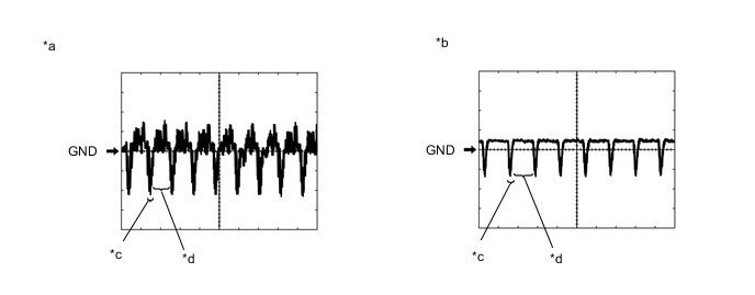
Reference (Oscilloscope waveform):
-
Waveform 1 (camera lens is not covered, displaying an image)
Item Content Measurement terminal F125-12 (V+) - F113-7 (GND1) Measurement setting 200 mV/DIV., 50 μsec./DIV. Condition Ignition switch ON, shift lever in R Tech Tips
The video waveform changes according to the image sent by the television camera assembly.
-
Waveform 2 (camera lens is covered, blacking out the screen)
Item Content Measurement terminal F125-12 (V+) - F113-7 (GND1) Measurement setting 200 mV/DIV., 50 μsec./DIV. Condition Ignition switch ON, shift lever in R Tech Tips
The video waveform changes according to the image sent by the rear television camera assembly.
Text in Illustration *a Waveform 1 (camera lens not covered, displaying an image) *b Waveform 2 (camera lens covered, blacking out the screen) *c Synchronization Signal *d Video Waveform
-
-
-
NAVIGATION ECU
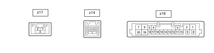
Terminal No. (Symbol) Wiring Color Terminal Description Condition Specified Condition z16-1 (B+) - z16-2 (GND) W - W Power source (+B) Ignition switch off 11 to 14 V z16-2 (GND) - Body ground W - Body ground Ground Always Below 1 V z16-3 (ACC) - z16-2 (GND) B - W Power source (ACC) Ignition switch off Below 1 V Ignition switch ACC 11 to 14 V z16-5 (SPD) - z16-2 (GND) B - W Vehicle speed signal Ignition switch on Wheel being rotated Pulse generation z16-16 (MIC+) - z16-2(GND) B - W Microphone voice signal See "Check Microphone" in Operation Check
- z16-17 (MIC-) - z16-2(GND) B - W Microphone voice signal See "Check Microphone" in Operation Check
- z14-1 (USV1) - Power source - - z14-2 (US1-) - Data signal - - z14-3 (US1+) - Data signal - - z14-4 (UGD1) - Ground - - z14-5 (USG1) - Shield ground - - z17-1 (LV1-) - Video signal (Digital) - - z17-2 (LV1+) - Video signal (Digital) - - z17-3 (LVG1) - Shield ground - - -
STEREO COMPONENT AMPLIFIER ASSEMBLY (for 8 Speakers)

Terminal No. (Symbol) Wiring Color Terminal Description Condition Specified Condition K47-1 (RL+) - K47-10 (GND) P - W-B Sound signal (Front Left) Audio system playing A waveform synchronized with sounds is output K47-2 (RR+) - K47-10 (GND) LG - W-B Sound signal (Front Right) Audio system playing A waveform synchronized with sounds is output K47-3 (WFR+) - K47-10 (GND) LG - W-B Sound signal (Front Right) Audio system playing A waveform synchronized with sounds is output K47-4 (WFL+) - K47-10 (GND) P - W-B Sound signal (Front Left) Audio system playing A waveform synchronized with sounds is output K47-5 (+B) - K47-10 (GND) G - W-B Power source (+B) Always 11 to 14 V K47-6 (RL-) - K47-10 (GND) V - W-B Sound signal (Front Left) Audio system playing A waveform synchronized with sounds is output K47-7 (RR-) - K47-10 (GND) L - W-B Sound signal (Front Right) Audio system playing A waveform synchronized with sounds is output K47-8 (WFR-) - K47-10 (GND) L - W-B Sound signal (Front Right) Audio system playing A waveform synchronized with sounds is output K47-9 (AMP+) - Body ground SB - Body ground Power source of stereo component amplifier Audio system playing 11 to 14 V K47-10 (GND) - Body ground W-B - Body ground Ground Always Below 1 V K47-11 (WFL-) - K47-10 (GND) V - W-B Sound signal (Front Left) Audio system playing A waveform synchronized with sounds is output K47-12 (ACC) - K47-10 (GND) GR - W-B Power source (ACC) Ignition switch off Below 1 V Ignition switch ACC 11 to 14 V